| Most of the older Z32s have problems with their clocks. The display gets too dim, or goes out altogether. With the cost of a new OEM clock above one hundred dollars, most opt to put in a turbo timer or some other small electronics in the prime console real-estate, install an audio head unit with a clock display on it and call it a day. Fixing the OEM clock is surprisingly simple if you have some soldering skills to replace some resistors buried inside it. NOTE: this process will not work for everyone due to the fact the old 181 ohm resistors may have failed to the point where they allowed too much current to go through the board and damaged some other component. It is definitely worth it to try, can't be made much worse.
Tools/Parts:
flat head screwdriver
soldering iron (not a soldering gun)
solder (rosin core)
2 180 ohm 1/2 watt resistors
de soldering wick (not shown) to help clean up excess solder
multi meter, not required but can be extremely helpful
Procedure:
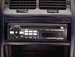
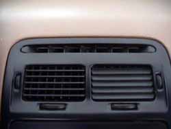
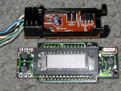
1. Remove the clock from the dash by removing the front console. There are two screws behind the trim plate above the top DIN slot (1.) and two more behind covers left and right of the top vents (2.). The clock is held in by 2 Philips head screws. Unscrew it and unplug it. Take the front and back covers of the clock apart by inserting the flathead into the slots located on the bottom of the display area (3.). Twist the screwdriver and it should loosen up the plastic tab. Do the same for the other side and the front plate will come apart.
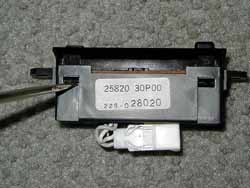
2. With the 2 covers removed, the plug will be on the back cover of the two halves. Forcefully press forward to remove it out of the slot that's holding it in (4.). NOTE: It can be rather hard to remove so go easy on it as well as remember the position it was on for re-assembly later.
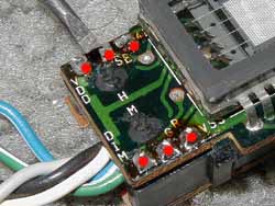
3. Separate the top and bottom boards. There are 6 pins to de-solder (red dots in 5.). De-solder them and carefully place a screwdriver between the black plastic and the bottom part of the board to CAREFULLY pry them apart. It will not come apart easily. If it is too difficult, try to remove as much solder as possible holding the 6 pins in place (6.).
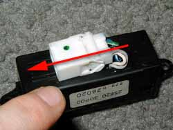
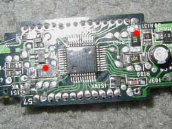
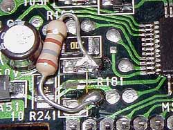
4. Take the board with the glass display and flip it around. Notice the 2 flat, black, resistors marked with a "181" on them (2 red dots in 7.). These resistors need to be removed. Actually, the only one needing to be removed and replaced is the one connected to the cathode heaters on the display. However, I would replace them both because if one fails then there is a possibility they both might be defective. Try to remove as much solder as possible holding the resistors in place. Remove the 2 "181" ohm resistors by removing or breaking them off the board with the flat head screwdriver. NOTE: Be careful not to slip which will cause the screwdriver to damage another part or scratch the traces (metal paths) on the board.
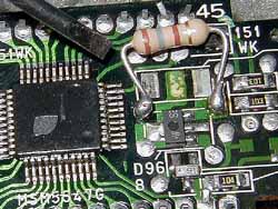
5. Once the old resistors are removed, measure the length of the new resistor wires to match the circular prints which are approximately 2-3 mm below the old resistor solders. I would not re-solder the new resistor in the same place as the old, because when they were removed, they may have damaged the traces under them (8.). Solder the new resistors onto the board carefully. Make sure the resistor wires aren't touching any exposed parts cause it might ground and/or short out components . Do the same for the other resistor (9.).
6. Put the top and bottom halves back together and re-solder the 6 pins. Place the plug through the back cover and snap it back into place. Place the clock snug into the back cover and then seal/snap together the front cover to combine the to halves. Go back to the Z, plug it in, turn the key to the 'On' position. If done properly, the clock should illuminate like new.
Originally published 12-10-2001
TruOmega
Back to TECH |