| The Z32 came with minimal alignment adjustments.
On the front, the only adjustment is the toe-in. Caster and camber cannot
be adjusted without special after market parts. The upper links, commonly
called A-arms, control the amount of camber. This is the amount the wheels
lean inward (negative) or possibly outward (positive). The more negative
camber, the better the car will corner. This comes with the price of more
inner edge wear on the tires, as the inside edge takes more travel abuse
then the entire tire will take under cornering. If the car is only for
racing, then numbers like -2.0 or -2.5 degrees of camber are acceptable.
For most people, it's not. The factory spec is -1.35 to -0.05 degrees *unladen*.
Laden alignment number should be -.5 to -1.5 degrees, I think this is the
best way to measure. I think the alignment specs have changed along the
way.. like in '92 according to the Hunter bench I get my alignment done
on. I need to verify the real numbers. The alignment specialist will know
the answers. Adjustable upper links are usually required when the car is
older and proper alignment specs cannot be met, the car has been in a front
end wreck and the frame wasn't straightened properly, or the car has been
lowered or the suspension geometry has been altered somehow to effect camber.
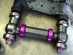
There are two basic styles of adjustable upper links: The Stillen 'slide
plate' design and the Japanese 'turnbuckle' design. I'll cover installation
of both, but all illustrations are of the Japanese "Midori" adjustable
upper links. This installation is on a '93 TT.
Special thanks to Paul (KC) for the doc this is based on
Timing:
The best time would be when any other suspension work is being done
that requires an alignment, or when proper alignment requires it.
Special Tools:
18" x 1/2" extension
14 and 17 mm 1/2" sockets
1/2" breaker bar
Torque wrench
Procedure:
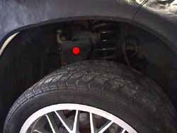
1. Lift the front end of the car high enough to stretch out the front
suspension (1.) and secure with jack stands on the frame rails.
Observe all safety precautions. Read the rest of the page and soak all
involved bolts and nuts with a penetrating lubricant. I recommend PB Blaster.
2. Remove the bolt connecting the upper link to the third link (red
dot in 1.) (1 x 17 mm bolt, 1 x 17 mm nut). The 17 mm nuts holding
the arm into the bracket and third member, along with the bracket to the
frame are all 'one use' nuts. A slightly misleading term, they can be re-used,
but they won't self lock again unless they are re-set by striking the top
side of them with a metal hammer. I generally don't bother with this, as
the torque specs are high enough to keep things from coming loose on their
own. Cleaning the nuts and bolts, then applying Loc-Tite will do the same
thing for people wanting to be slightly more cautious. The wheel will sag
a bit more when the third link comes loose from the upper link.
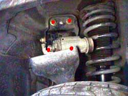
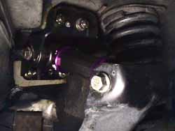
3. Lift up the upper link a little and remove the two lower nuts holding
the bracket to the frame (lower red dots in 2.) (2 x 14 mm nuts).
The 'bolts' are part of a plate assembly in the engine bay, so there is
no bolt head to put a wrench on. Make sure to be fully seated on the nuts
before trying to remove them, they are easy to round off. A 18" x 1/2"
extension covered with a towel or rag to prevent scratching the fender
paint on a good sized breaker bar make this easier then trying to twist
a wrench inside the wheel well. Remove the upper nuts holding the bracket
to the frame. If these nuts have never been removed before, the self locks
are binding the bolt properly. Air tools might have some difficulty with
this, just use the breaker bar to get them started & the air tool to
finish them off.
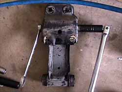
4. Remove the bracket from the frame. Remove the upper link from the
bracket ( 3.) (1 x 17 mm bolt, 1 x 17 mm nut).
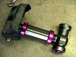
5. Use the upper link bolts to check the length of the new adjustable
upper links against the factory upper links. This gets the length in the
ballpark to get the car over to the alignment rack.
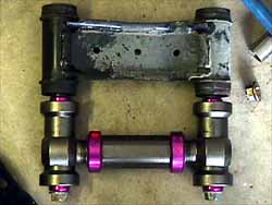
For the Japanese style links (Midoris): Twist in both ends in until the link is
as short as it can get without binding. Keep in mind one end isn't 'righty
tighty', but backwards for the link to work properly. Get the link properly
situated, as there is a front and back, and left and right, they should
be marked as what side and end each are, at least the Midori's are (red dot
stickers go toward the engine, longer side goes forward). Keeping
the same 'alignment' slowly twist the center section until the link extends
to the same length as the factory upper link. Use the bolts to check the
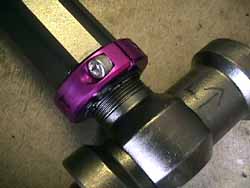
length (4. & 5.). Loosen the locking collars (6.)
(2 x 5 mm hex) and twist them around to where they will be accessible once
mounted back in the car.
For the Stillen style links: Stillen says their links are symmetrical
and work in any
orientation. However this seems to be the only correct working orientation:
1. Angled-in zerk - inside end and facing down
2. Straight-up zerk - outside end and facing up
3. Adjustment bolts - heads are facing up
4. Adjustment gear - toward the rear of the car
Loosen the locking nuts (4 x 1/2") and run the ends to the appropriate
length using the upper link bolts to check the correct length. Torque the
lock nuts to 15 ft-lbs. Thoroughly cover the shafts of the link bolts with
high temp, non lithium, water resistant chassis/bearing grease. Stillen
recommends against white lithium grease, they also recommend relubing ever
10k miles to avoid bushing squeak.
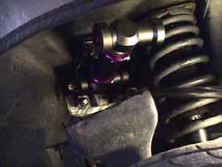
6. Attach adjustable upper link to the bracket using the bolt with the
"9B" marking on the head of the bolt (this one is a little thicker than
the other one which should be marked "9") and a new nut (7.) (1
x 17 mm bolt, 1 x 17 mm nut). Torque to 65-80 ft-lbs.
7. Reattach upper link bracket to inner fender well (8.) (2 x
17 mm, 2 x 14 mm). Torque the 14 mm to 43-58 ft lbs. Torque the 17 mm nuts
to 80-94 ft-lbs.
8. Attach the other end of the upper link to the third link using the
bolt marked "9". (9.) (1 x 17 mm bolt, 1 x 17 mm nut). Torque to
65-80 ft-lbs.
9. On the Japanese style: Tighten the locking collars to 14-21 ft-lbs
(2 x 5 mm hex). On Stillen style: Use the grease fittings to push more
white lithium grease into the ends of the links to keep them very well
lubricated. The Japanese "Midoris" have bearings in the ends and don't
need grease.
10. Lower the car, get an alignment done ASAP.
REV 2-21-02
Dallas DamonZ
Paul (KC)
Linear
rockjaw
Back to Tech page |