| Below is an Air Flow Graph I made for a Toyota MAF I was working with.. I used a Superflow Flow bench and charted the Air Flow CFM to Voltage Output.. This chart is Typical of Flow Meters, as the Output is not 'Linear'.. That is about 2 Volts is 22 CFM, but 4 Volts is about 180 CFM. 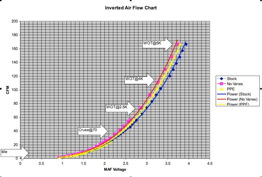
With the 'Curve' of the Flow Meter, you can not just 'Add' the voltage of the two MAF's .. you have to take the Voltage input, Reference a Curve in the 'Combiner' so it will now output about 2.6 Volts if BOTH MAF Meters are reading 22 CFM. However.. with this Senario, you are using TWO Flow Meters to give the same results of one meter.. So you will still hit the Limit of 5 Volts with Two Meters and a Combiner, and One meter no Combiner at the Same time.. No Advantage. The Scenario Used, is to use TWO MAFS, ( One each Side ) only hook the Left Side of the Intak's MAF to the ECU, ( This will cut the MAF Reading form the ENTIRE Engine in Half) and then put an Air Flow Chart in the ECU that will now be set up to 'Double' the Readings that are coming in from the 'Single MAF Set up'..
The 'Problem' with this is the Left Side of the Intake, has the Idle Circuit in it, so SOME of the Idle Air will be Doubled, when it actually is not proper to do so.. So the Fix is to use a 'Combiner', that will have the Air Flow Chart, for the MAF inside, and use TWO MAFs on the Intake.. Take the Air Flow Readings from each MAF, Calculate the Amount of Air Actually Injected in the Engine, then the Combiner will Go to it's look up chart, and Output the Reading as 'Half Air Flow'.. Then the ECU recieves the '1/2' Air Flow Number and goes to it's Look up Chart ( Now Modified as Well ) and get the Proper Amount of Air injected into the Engine.. This is all a Big Work Around the 'Re-Scale' the Original Single MAF that would Peak Out at 5 Volts before your Engine was at the Max Amount of air you were able to Injest.. Another way to do this is to Change the MAF and ECU air flow chart to another MAF that will naturally flow more Air.. before hitting the 5 Volt Limit of the Sensor.. There is a Write up here somewhere about using a FORD MAF.. again you have to change the Chart in the ECU.. Back to your Original Thought, of using a Different Combiner.. The Combiner must have the SAME Air Flow Chart, as the MAF it's designed for.. If you do not know the Chart Curve, it will do no good.. HOWEVER, you could use the 'Wrong Combiner' if you re-Worked the MAF Chart in the ECU to Fix it, then all would be well.. I have no easy way to figure out what the 'Modified Air Flow Chart' would look like in the TT ECU.. Cj
|


 Re: Dual MAF mod? -