| I usually avoid accepting these clocks for repair. They are such a PITA to work with. I would rather repair three speedometer gauges than one clock. To repair the clock to a reliable condition requires some extensive work. 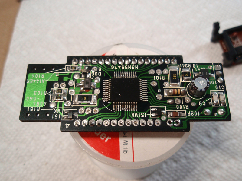
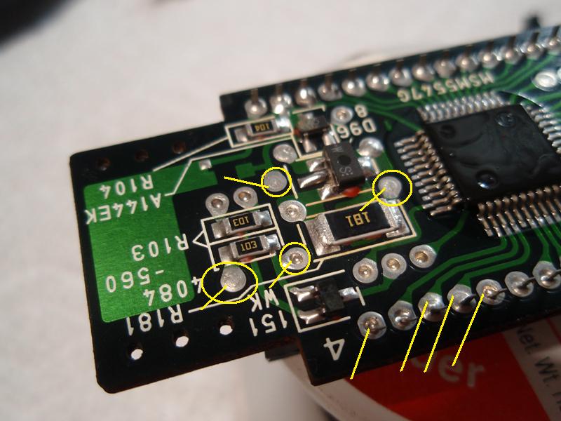
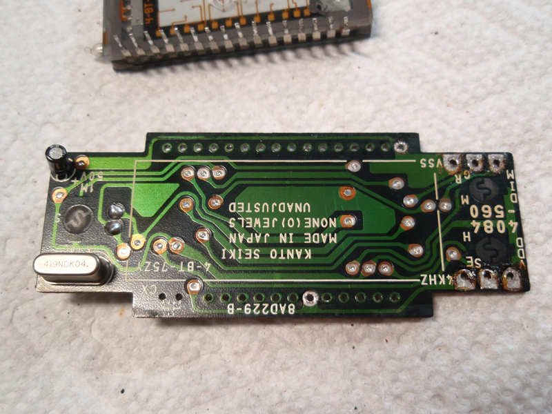
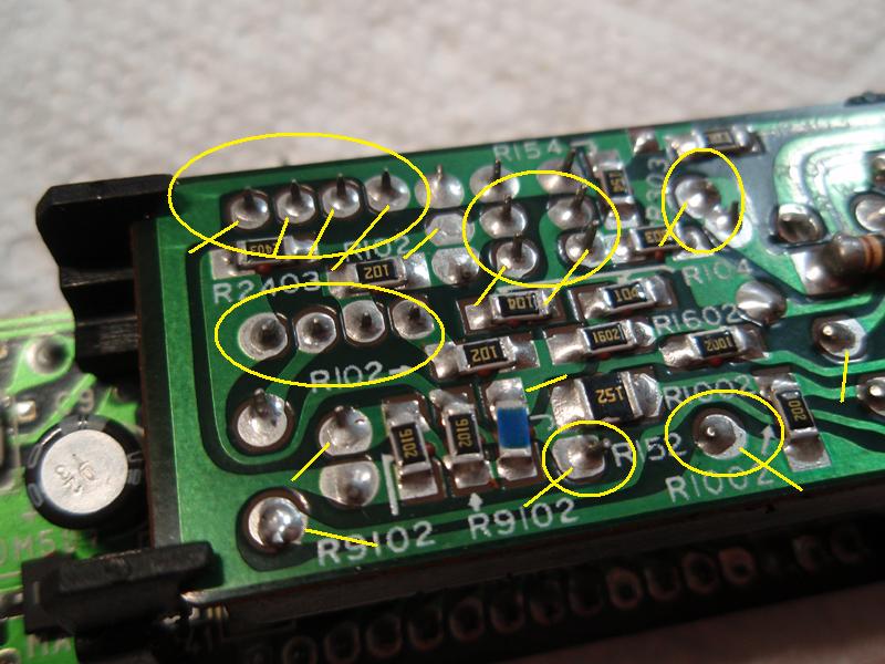
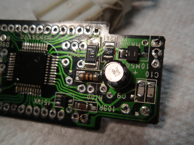
The clock is riddled with solder failures at both component leads and feed through plated holes. In the following pictures I have only pointed out a few of these examples as there are way to many.
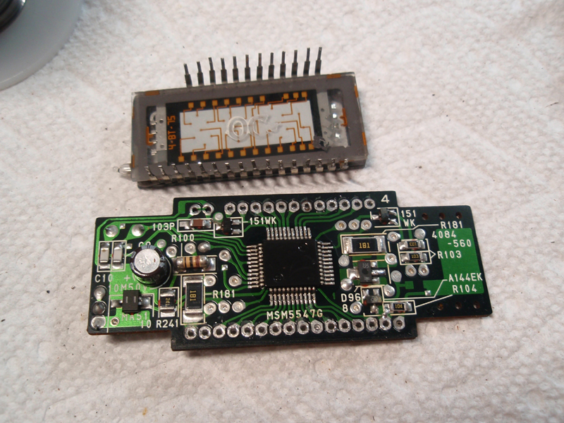
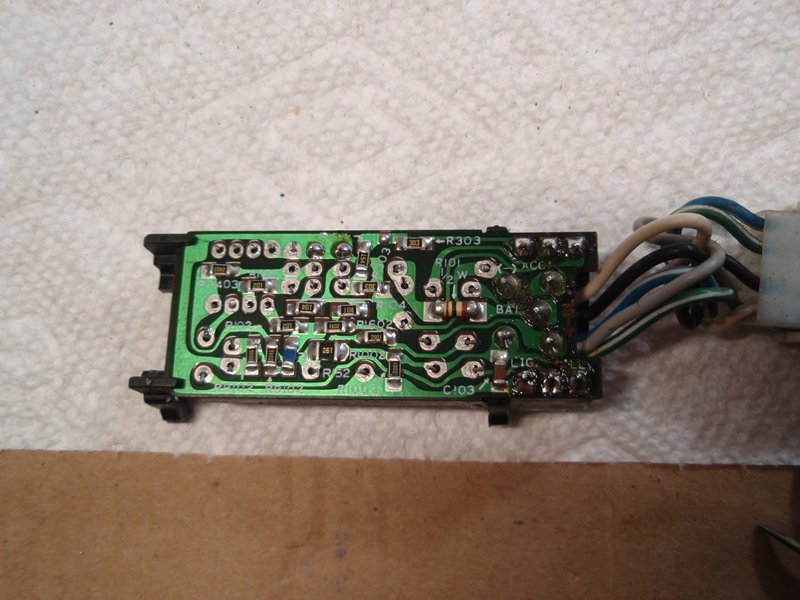
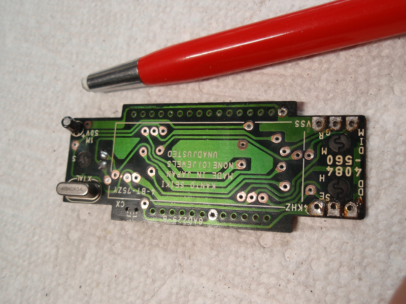
Display removed. Be careful. The display pins are very fragile. They are not rigid like IC pins.
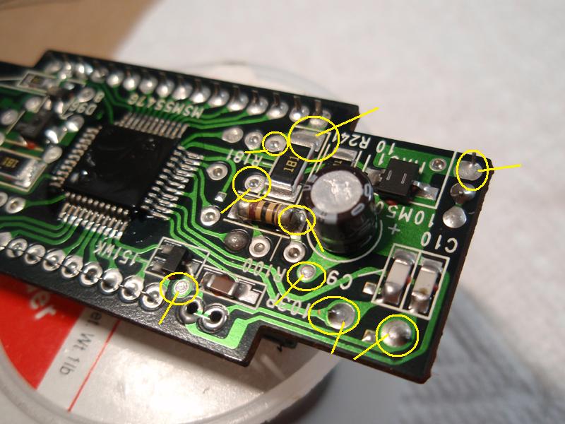
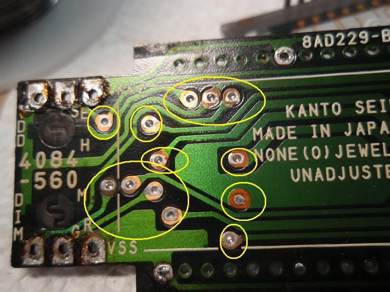
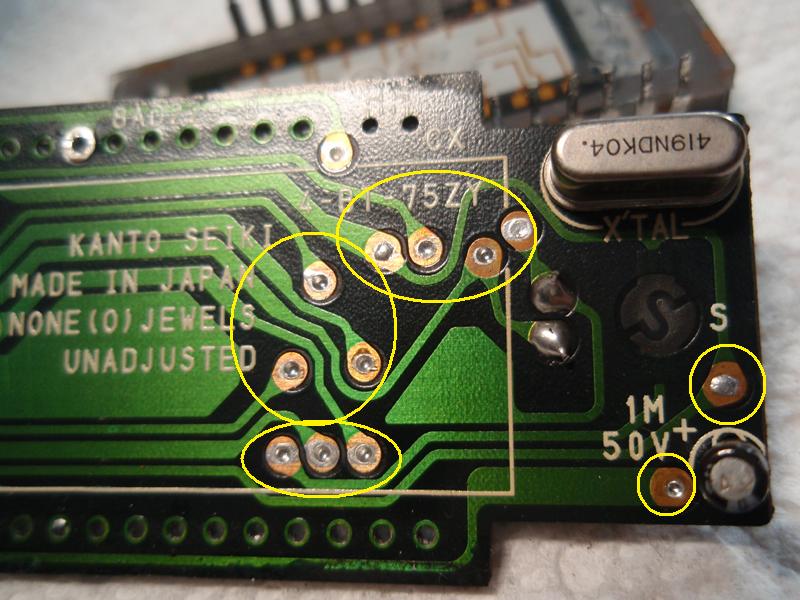
Here you can see under the display where there are more feed through plated holes with failed solder connections. At the factory the board is passed through a wave solder on only one side. This has caused the solder to not flow completely on this side of the board's plated through holes. During repair you should solder both sides of these holes.
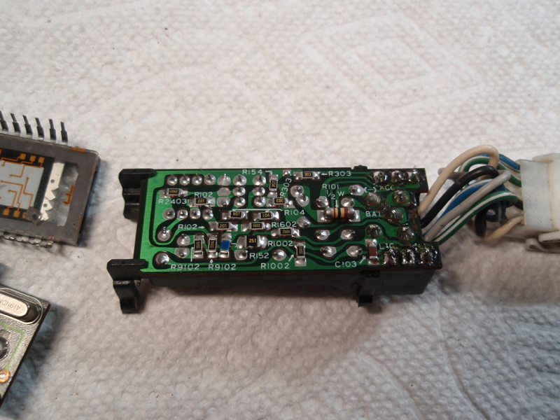
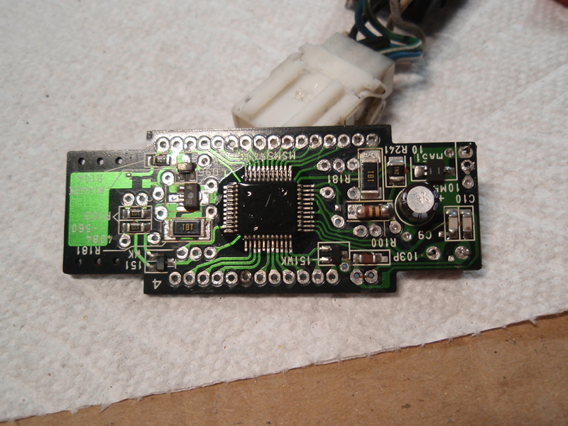
The USDM clocks have two boards. This second board is also riddled with failed solder connections.
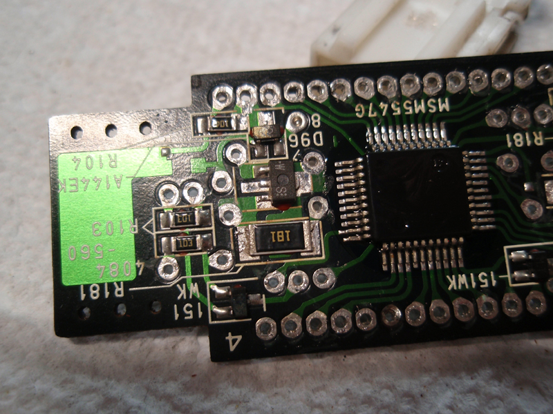
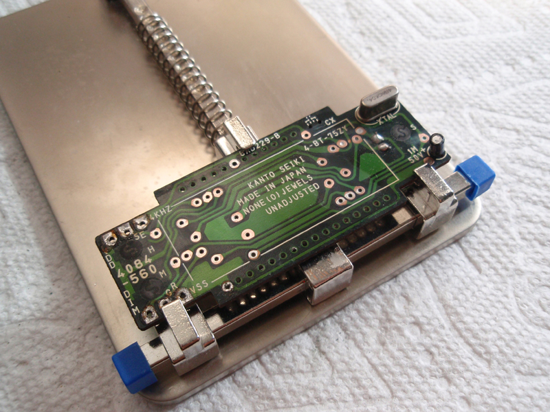
What's needed first is to remove as much of the old solder as you can from both boards. These pictures are only for examples. I removed more of the old solder than what is shown here.
Once you have removed the old solder, the feed through solder pads need to be cleaned so that the new solder will adhere properly. For this I use an abrasive pen. The pen's core is a fiberglass rod made up of hundreds if not thousands of individual fiberglass threads. Use caution when using this pin. The micro-small fiberglass threads break off while using it and they can lodge in your skin. They are very painful and may require you to use a magnifying glass and very fine tweezers to pull the splinters out. The best thing to do is wear latex or similar gloves when using them. You might also want to wear a dust mask as the pen can also give off a fine fiberglass powder in the air around the work surface. Never touch your face or eyes while using this pen. Wash your hands immediately after using it.
The board ready to have new solder applied.
It works again!
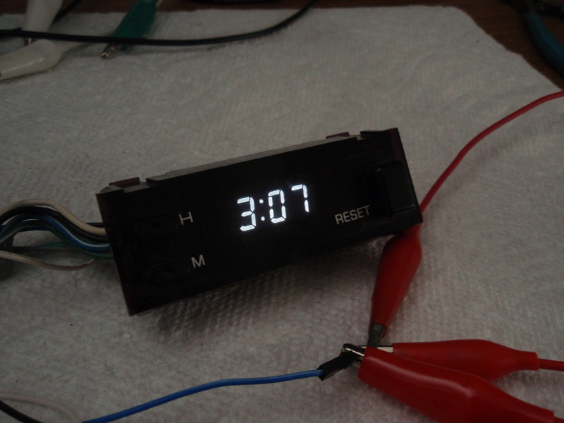
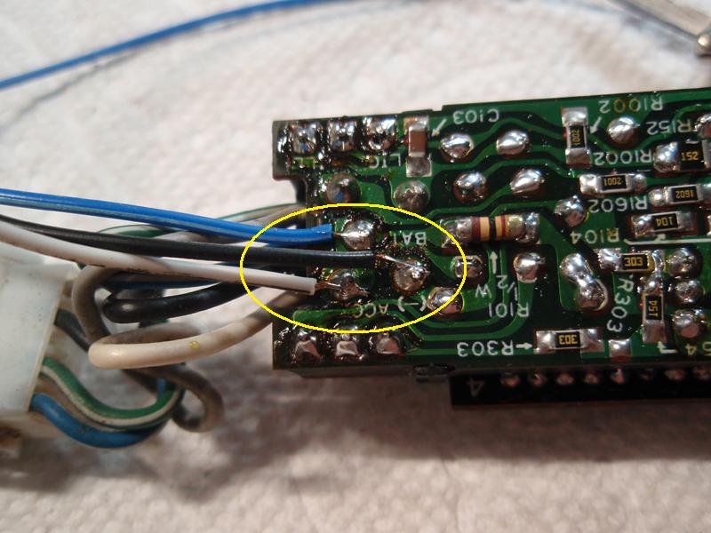
To power the clock only requires three of the wires that go to it. Here I attached three wires to power the clock. The blue and white wire are 12v B+. The black wire is ground. Illumination of the clock is controlled by the clocks green/white wire but is not needed. It's a negative control line which is why. Meaning, the more negative the line is, the more dim the display gets.
Important notes: The clock's connectors in the car and on the clock have different color codes. As an example, the red/black wire at the connector in the car connects to the green/white wire at the connector on the clock. As if tracing wires and voltages this way isn't bad enough, the USDM factory service manual is again incorrect as it shows a picture of a JDM connector and color codes making it impossible to trace the pin outs correctly for our USDM clocks.
 www.mytwinturbo.com Nissan Data Voice - The first Nissan diagnostic software with a voice!
 Nissan Data Voice on YouTube Download my Nissan 300ZX Vin/Model Lookup. |


 Clock repair. -