| 300ZX Cruise Control (ASCD) Woes I have owned my car for a number of years, I had never used the cruise control but on a recent trip I attempted to engage it with no luck. I decided to trouble shoot the system to determine why the cruise control would not turn on and engage. I own a USA version 92 twin turbo with manual transmission and automatic A/C. According to the Field Service Manual (FSM), whether you have automatic or manual A/C and weather you have an automatic or manual transmission determines where various components of the ASCD are located on the car and exactly which components you have. The automatic has an inhibitor switch and park/neutral relay that the manual car does not. The manual car has a second ASCD cancel switch that works with the clutch pedal. Both cars have a cancel switch which works with the brake pedal. I first turned to the FSM for 1992 and it advised checking various wires on the ASCD control module. The problem was in looking at the diagrams in the FSM, I could not tell where the module was physically located. I searched on the net. Some said it was in the passenger side kick panel. It wasn’t. Only the ASCD hold relay is there. Some said in front of the battery. Not there either. The sketch in the FSM makes it look it is neat the right front shock tower. It isn’t. The official Nissan parts diagram as placed on line by Courtesy Nissan and others makes it look like it is midway across the firewall and maybe in the engine compartment or on the other side of the wall under the dash. It is none of these places. It is in fact located directly under the ECU in the passenger foot well. So yes, you have to take up the floor mat, carpeting, and wood panel and then unbolt the ECU to gain access to it. Interesting enough the 1990 FSM has a nice big diagram showing exactly where the ASCD module is located but this diagram is not included in the 91-96 FSMs. It should also be noted that the trouble shooting instructions in the 1990 manual differ somewhat from later FSMs. The 96 FSM contains a nice write up of the operation of the Cruise Control which earlier manuals do not. Since I don’t have a consult I had to use the “old school” trouble shooting method using just a multi-meter.
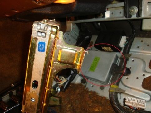
The ASCD module is circled in red in the picture.
The 92 FSM offers a sequence of tests that are very logical starting with gaining access to the cruise control module and testing for voltage (or absence of voltage) on various wires plugged into it.
Before you start this process however, I suggest getting the easiest tests out of the way first, which do not require any test equipment. My first test would consist of glancing at the Speedometer while in motion to see if it is functioning correctly. If it is, you have just determined that the speed sensor located on the transmission is functioning correctly. About ¾ the way through the FSM troubleshooting process for the ASCD, it suggests testing the speed senor by hooking a multi-meter to wire number 7 of the ASCD Control Module and then jacking up the rear of the car and slowly turning the wheel to see if the needle or readout on the multi-meter fluctuates with the rotation. Since you have already confirmed that the speed sensor is working however, all that this test actually does is determine whether or not the signal that is going to the speedometer is then being forwarded to the cruise control module or not. If it is not, it would indicate a broken wire or connection going to the module. What are the odds though that of all the wires in the car this one and only this one decides to break? I think very remote - so I would suggest leaving this test to dead last. If the speedometer and the cruise control both do not work then you have found your problem with the speed sensor. The next thing I suggest you do is simply to try and beep the horn. If both the cruise control and the horn are not functioning, it indicates a blown horn fuse, stuck or broken horn relay or both. The fuse can be checked visually or with the multi-meter. If the fuse is good you might as well go ahead and replace the horn relay. The 92 car shares the horn fuse and relay with the ASCD. In fact there is no ASCD listed on the fuse cover at all. The next thing to do is note whether or not the first (top) of the two cruise control lights illuminates (the one that says “cruise”) in the instrument cluster when the cruise control switch on the left hand instrument panel control stalk is switched on. If it does not illuminate it could be a burned out bulb but it could also mean that 12v is not getting to the control module and you can then proceed to the electrical tests to determine which the case is. (The light under the “cruise” light says “cruise cont” when illuminated. It and comes on when cruise lever is pushed down and the module is getting power.) The next easy thing to look at is the short vacuum hose that runs between the actuator assembly and the bellows assembly containing the cruise control cable that runs parallel to the throttle cable. The vacuum hose should be attached to both units and not have any holes or splits in it. If you want to test the bellows assembly you can disconnect the vacuum hose at the actuator and suck on it. This should cause the cable to retract. The actuator and valves within it are nothing more than a vacuum pump supplying vacuum to the cable mechanism when needed. After these three tasks are performed it starts to take more time and effort. The next test I suggest is a visual one, of the two (on manual cars, one on automatic) green rubber stoppers that interact with the cruise control cancel switches located on the brake and clutch pedals. These are made out of a green rubber gel. In time, they can become brittle and then disintegrate falling in pieces and leaving a hole in the brake or clutch pedal shafts where they used to be attached. The plunger on the cancel switch that used to be kept retracted when the brake and clutch pedal were not depressed and the stoppers were present, will then be extended all the time and the cruise control module not allow the ASCD to engage.
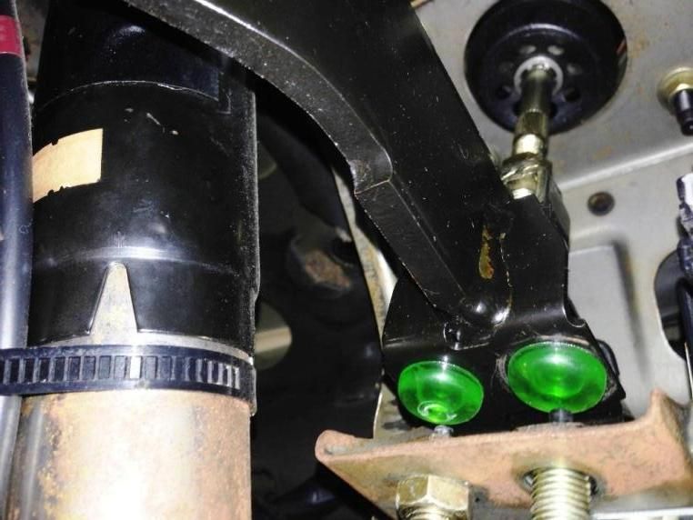
(Clutch and brake pedal green stoppers – picture copied from internet) In order to look at the stoppers without removing the underside of the dash or contorting your body so that you can put your head upside down under the dash, you can do as I did and go the dollar store and get a compact but still decent size mirror. I was able to angle the mirror on the driver’s foot well floor and with a trouble light under the dash I was able to locate the stoppers on the pedal shafts. Then by pushing on the pedals I could see if the stoppers are intact and if they pushing in the plungers on the switches when the pedals were released.
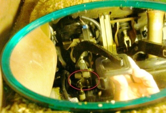
(In the picture there is a red circle around the stoppers and actuator plungers in the mirror reflected image.) The preceding paragraphs just describe visual test to see if the stoppers are present. If they are, then an electrical test of the switches of the function of the switches will need to be made. If the stoppers are missing they need to be replaced or some other form of fix needs to be made to plug the holes in the pedal shafts. Replacing the stoppers is not a real easy task to perform due to their location. Basically you have to remove the bottom of the dash on the driver’s side and some of the A/C ducts as well. Then using needle nosed pliers squeeze the tab until you can make it fit into the pedal shaft hole, while the pedal is depressed. There are a number of write ups on the process on the net. If the stoppers are there and solid, then you can start going down the FSM trouble shooting process by first exposing the cruise control module which is located under the ECU in the passenger side foot well. The FSM indicates that you must remove the cruise control module from the floor (to gain access to the lower row of wires) and leave the module plugged in while testing the leads mentioned. I found the results to be the same whether the unit was connected or not. The thing to remember in troubleshooting the wires on the module is that you are not actually testing the module itself in any way. You are only testing whether or not voltage and signals are getting to the module through the wires or not. There is no trouble shooting process for the module itself in the FSM.
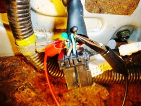
If you end up going through the complete trouble shooting sequence in the FSM without finding any problem, the FSM then suggests that you replace the module as a last step since you have by that point eliminated all the other components in the cruise control chain. Note that the 300zx uses different part numbers on the modules depending on whether the car is an automatic or manual and different years can use different modules as well. Only a couple of the new ones are still available new from Nissan. Nissan also changed their part number system so the part number on your module will not match the part numbers of the new modules. You will need the part number of the old module however if you are searching for a used one. The next steps all involve testing for voltage or lack of voltage on wires. I went to K-Mart and in the sewing section there was a box of Singer straight pins. These are short thin pins with plastic tips on them that are in colors. They are easy to push in the wire or in the rear of the harness connector and I always used the pins with the black tops for ground wires which helped keep things straight with the multi-meter.
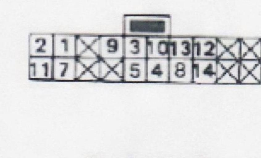
 I have placed a list of the wires that get tested in the FSM below with the number of the wire, color code of the wire and the parts of the system that are being tested. Cruise control module wire color #3 B - solid black - Ground
#7 Y/G - yellow with green stripe- Speed Sensor input via the Electric Speedometer
#1 G/OR - green with orange stripe - ASCD steering switch – Resume/Accel
#2 G/Y - green with yellow stripe - ASCD steering switch – Set/Coast
#4 G/W - green with white stripe - Hold Relay, Cruise Control Light
#5 G/R - green with red stripe - ASCD Cancel Switch (on Brake Pedal Shaft) ASCD Cancel Switch on Clutch Pedal Shaft (on Manuals), Inhibitor Switch (on Automatics)
#8 L/W - blue with white stripe - to ECM Control module
#9 L/B - blue with black stripe - ASCD Actuator Vacuum Pump motor
#10 L - blue - ASCD Actuator Pump Air Valve
#14 B/R - black with red stripe - ASCD Actuator Pump Release Valve
 The picture is of the connector that plugs in the ASCD module. It is from section EL of the FSM. Tests Power at Control Unit – Key - On, Connector connected – terminal 3 (ground) to 4, should be 12V Power between 3 (ground) and 5 with clutch and brake pedals released should be 12 V. With either pedal pushed in – should be zero V. This is a test of the two cancel switches. If either one does not pass the test it is either faulty or it needs to be adjusted so that the plunger is fully pushed in by the stopper pad for that switch. Make sure each pair of switches on the pedal shaft is set to the same height; otherwise one may stop the other from working. These switches are always suspect as problem sources since they are in constant use from pedal movement whether you are using the cruise control or not. Power between 3 (ground) and 2 - Turn and keep pushed down set/coast switch, key off, should be 12V. Power between 3 (ground) and 8 (input to ecu) - key on, connector connected, should be 0V. Resistance readings from 8 to 9 (5-45 ohm), 8 to 10 (approx 65 ohm), and 8 to14 (approx 65 ohm). Connector disconnected, key off. If you have gotten to this point without finding a problem then it is time to test the cruise control actuator assembly and cable electrically.
The FSM procedure is to disconnect the wire harness at the actuator. You will then be applying 12V from the battery to a male pin in the connector attached to the actuator, while others are attached to ground. The four pins are labeled: 1,2,3, and 4. With the positive 12 volts applied to pin 1 and the negative (ground) wire attached to pin 4, the vacuum pump should be turned on which you can hear. If that occurs, then the FSM suggests tying all three pins 2, 3 and 4 to ground. With 12 V applied to pin 1 with pins 2, 3, and 4 grounded, the cable should start retracting. When the grounds are disconnected then the cable should extend. If this does not happen then the actuator assembly is bad.
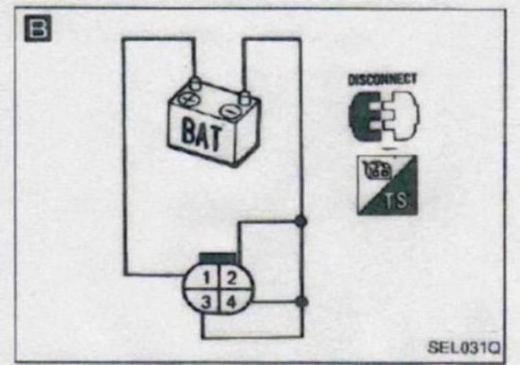 The picture shows the numbers on the connector that goes to the actuator. It is from section EL of the FSM. 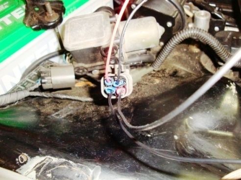
I crimped on some connectors to wires in order to press them onto the male ends in the ASCD connector in the engine compartment. With my car I ended up having two problems. First the horn did not work. I replaced the horn relay and the horn was then fixed. Replacing this relay also enabled the second of the two cruise control lights on the dash to illuminate when the cruise control stalk was flicked which was not formerly the case. The cruise control still did not engage however. In testing my actuator as described above, it failed the electrical test. The cable simply would not retract even though the vacuum pump was running. It was probably one of the two valves that work with the pump. Component parts are not sold separately for the actuator, it is sold as one assembly. A used replacement off of eBay, however saved the day for me. There are two actuator part numbers for the Z32 300zx. One is for the turbo models and one for the N/A. I believe them to be the same except for a bracket on the side of the actuators. The turbo has a small metal bracket that is longer than the N/A one and had an extra hole in it for mounting the tab of an electrical connector used on a turbo part in it. If your actuator passes the electrical test then you are basically down to two possibilities. One is the wire running from the speedometer to the cruise control module that carries the signal from the speed sensor and requires jacking up the rear of the car and then turning the rear wheels with a millimeter attached to the wire at the module while looking for fluctuations in the readings. The second possibility is a defective cruise module itself.
I did not have to get this far in my trouble shooting adventure. If I had, I think that I would have chosen to replace the module. I view the likelihood of the wire leading to the module carrying the speed senor signal as being broken (with a working speedometer) as being extremely remote. On the other hand, having peeked inside the module case and seen a circuit board jam packed with components being subject to cold, heat, and vibration I would suspect this item as a higher probability of failure. It does not help that the module is pan- caked directly under the ECU with no air circulation getting to it either. Different years of 300zx have different part numbers for their modules and there are different numbers for the turbo vs. non turbo cars. Only a couple of the variations are still available new from Nissan. It should also be noted that Nissan changed its part numbering system so that you will have to actually look at the part number on your unit in trying to match it to another used one. I hope this write up helps anyone having cruise control issues. Good luck with your troubleshooting.
|


 300ZX Cruise Control (ASCD) Woes -
  15:23:46 01/30/16