| Following is what I used as the procedure to replace and install the rear HICAS tie rod ball joints and the inner tie rods on a 1990 300ZX Twin Turbo. The title of this should have been "Use the right tool for the right job" because having the right tool makes all the difference in easily removing a ball joint. With it and a little innovation I was able to press out/in the ball joints on the rear tie rods fairly quickly and without any use of a torch or heat. I did both of these jobs at the same time. But if you were only replacing the inner tie rods you don't have to separate the tie rod from the ball joint. However, you would need to do things a little differently. See Michael12's old inner tie rod write up for details of doing that without separating the joint. Although I found separating it to be quite quick and easy. Once again, the right tool makes all the difference. Also, special thanks to member Sawbonez as I used a makeshift tool he mentioned in his previous write up on the ball joint replacement. Where my procedure differed is that I was not able to break the joint loose with just a C-Clamp and heat, even after several hours. In fact I only succeeded in expending a lot of energy and warping an industrial iron C-clamp in the process so proceeded to figure out a way to make the press tool that was made for the task work on our cars. 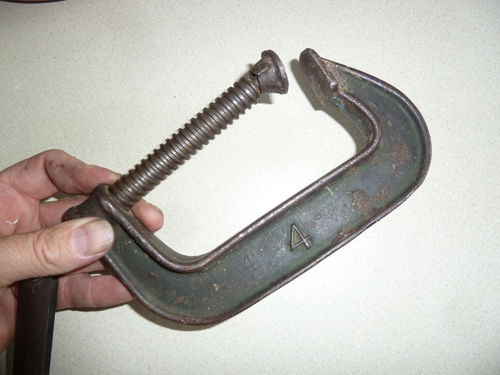
Estimated Time to do job:
4 - 8 hours for both tasks. Time will depend on how fast you work and whether you've removed your struts before and are familiar with that task. (I have) Time will also be significantly less if only replacing inner tie rods as you will not have to press out joints or remove struts to make room for press tool. Replacing the ball joints and tie rods does require lots of tools and makeshift tools to complete so be sure you have/borrow them before starting. Tools/Parts Needed:
- Floor jack
- Ramps or at least two 2" x 8" at least 18" long (for driving the front tires on to elevate the car so that you can lift the rear high enough and not scrape the front spoiler on the ground)
- One ~5" and one ~15" 2 x4 pieces of wood (used to make removing the struts easier which is needed to make room for the ball joint press tool)
- Wheel chocks
- Jack stands (2)
- A work light
- Sockets: 8mm, 10mm (optional 8mm and 10mm nut drivers highly recommended to speed trim removal), 12mm, 14 mm, 17mm, 19mm, 21mm deep (for lugs), 3/4", 7/8" deep
- 1/2" ratchet
- 3" 1/2" extension (to aid in removal of interior strut bolts in recessed compartments)
- 1/2" Torque wrench (up to 100lbs.)
- Wrenches - 12mm wrench (ratcheting recommended), 13mm, 17mm, 19mm
- (2) 32mm wrenches or crescent wrenches up to 32mm (standard width wrench, can't be a monster size wrench)
- One crescent wrench that can go up to 38mm (can be any width) (not shown in pic below)
- 18" Breaker bar
- 12" 1" diameter pipe (to put on end of ratchet or breaker bar for additional leverage, ~$6 at Home Depot)
- 12" 1-1/4" diameter pipe (to put on end of large crescent wrench for additional leverage, ~$6 at Home Depot)
- 3" long 1 1/4" I.D. pipe fitting (Home Depot, Lowes, etc.)
- 3/4" Ball joint separator (Harbor Freight ~$20, less if you pick one up on sale)
- Long needle nose pliers (to pull cotter rings)
- Medium flat head screwdriver (to scrape old gasket/sealant off ball joints)
- Medium Phillips head screwdriver (interior trim pieces)
- Rubber mallet (optional: helps when tapping end links back on and removing and nudging strut back into place)
- Duct tape
- PB Blaster or other lubricant
- Tube of Anti-sieze
- Tube of Blue threadlocker
- Tube of black RTV sealant/gasket maker
-You will also need a random nut or small socket that will be needed to assist in pressing out the ball joint. (I used 1/4" 5/32 socket) * Unless you have an extra set of arms, you will need an assistant (wife, girlfriend, adolescent, buddy, neighbor etc.) at a few times to briefly help hold or align items. Optional: Impact wrench to speed removal of lug nuts 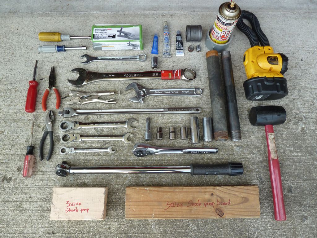
To press out the ball joints you will need to rent some tools (they're free when you bring them back):
I had to go to two separate auto parts stores to get what I needed. Pic below shows the adapters you will use from each set along with the pipe fitting, a random nut and small socket that are needed. - 23 Piece Powerbuilt Ball Joint Press (Advance Auto, note, the more common smaller 6 pc. set will not have the middle adapter shown below the pipe fitting that you will need. )
- Honda Ball Joint Adapter Set OEM #27164 (Autozone)
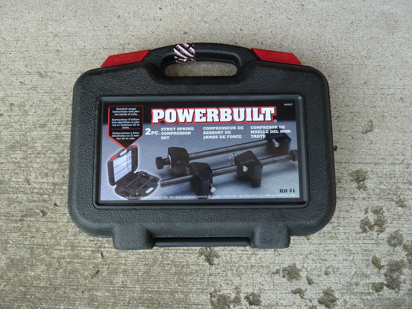
- Strut Spring Compressor (Any auto parts store) 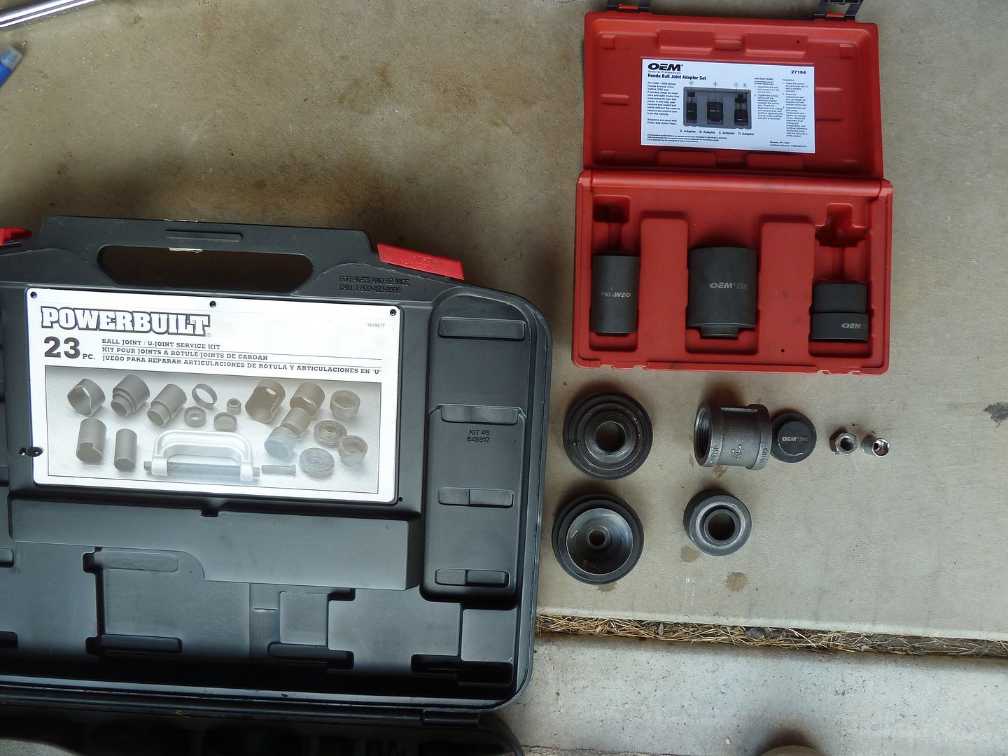
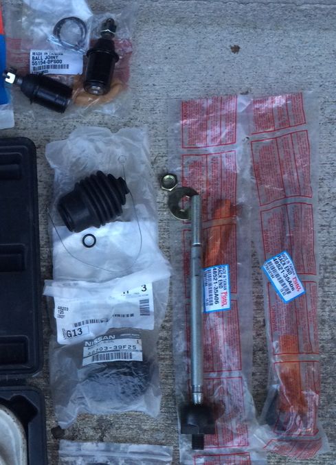
HICAS Ball joints - SPD 55154-0P800
HICAS Inner tie rods - SPD 48521-35A06
Tie rod boots - Nissan 48203-39F25
Ball joint rear cap/oil seal (if needed) Nissan 43030-30P01 Preparation for pressing out joints: 1. Drive your car fully up on the pieces of wood or car ramps. Chock the front of the wheels if using wood. Slide the floor jack under the car from the front. 2. Loosen rear wheel lug nuts using 21mm socket. 3. Jack the car up from the rear using the rear differential as your jack point then insert jack stands at the rear jack points on each side and raise the jack stands at least 2 clicks. 4. Remove the rear wheels. 5. Remove the ball joint's rear 12 mm locking bolt and oil seal. Then straighten and pull out the cotter pin using pliers and PB Blaster if needed. (if the cotter pin won't budge inserting an ice pick or small nail in the loop of it to pull on can help. One of mine came out really easy, and the other took a little elbow grease.) At this time, I also sprayed around the rear edges of the joint with lubricant in the hopes it would soak in around the ball joint to aid in removal. After removing the cotter pin, loosen the front 17 mm nut with breaker bar. 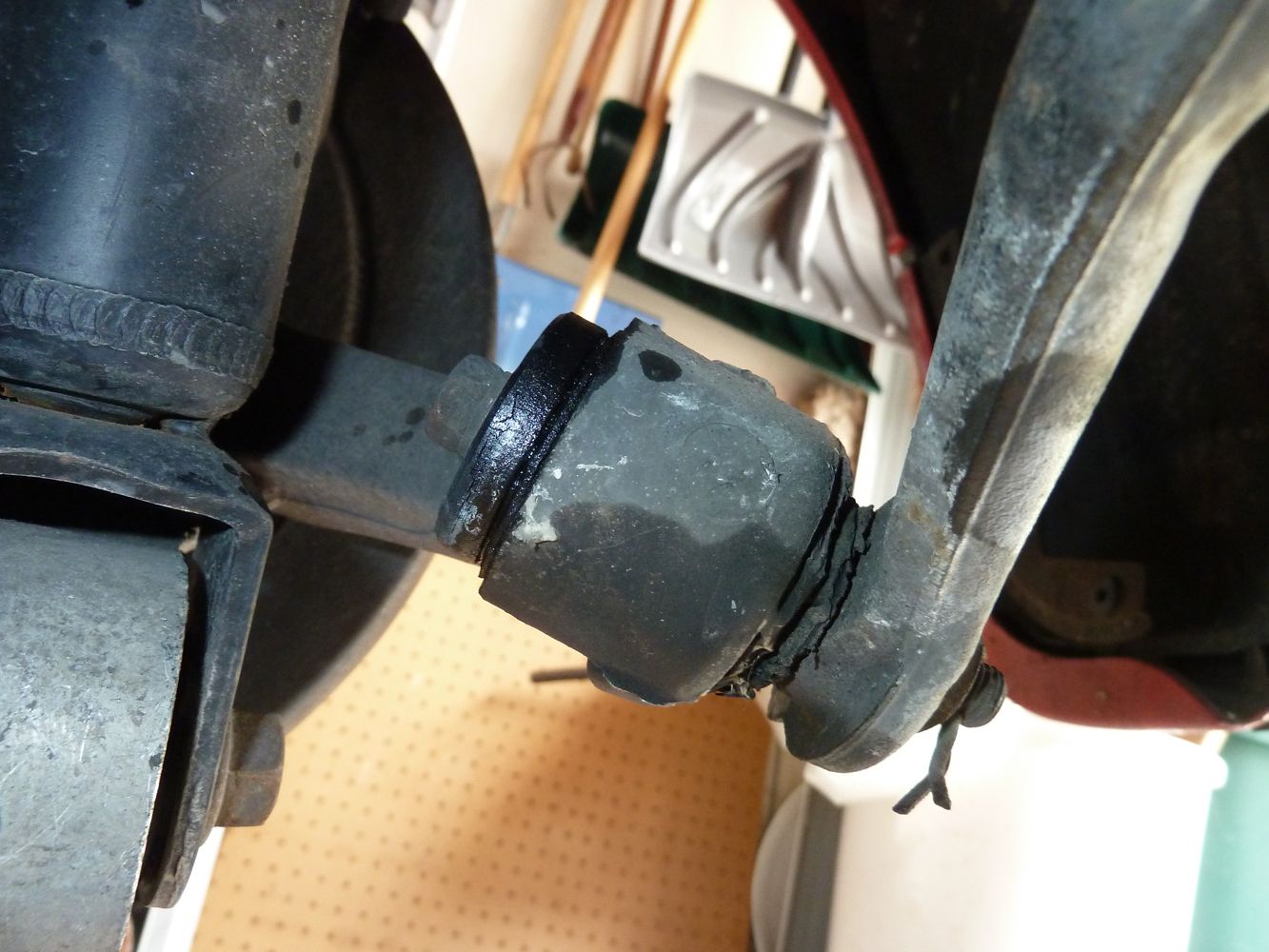
6. Unscrew the nut so it's flush with the end of the bolt. This will give the separator tool something wider than the bolt end to press on. 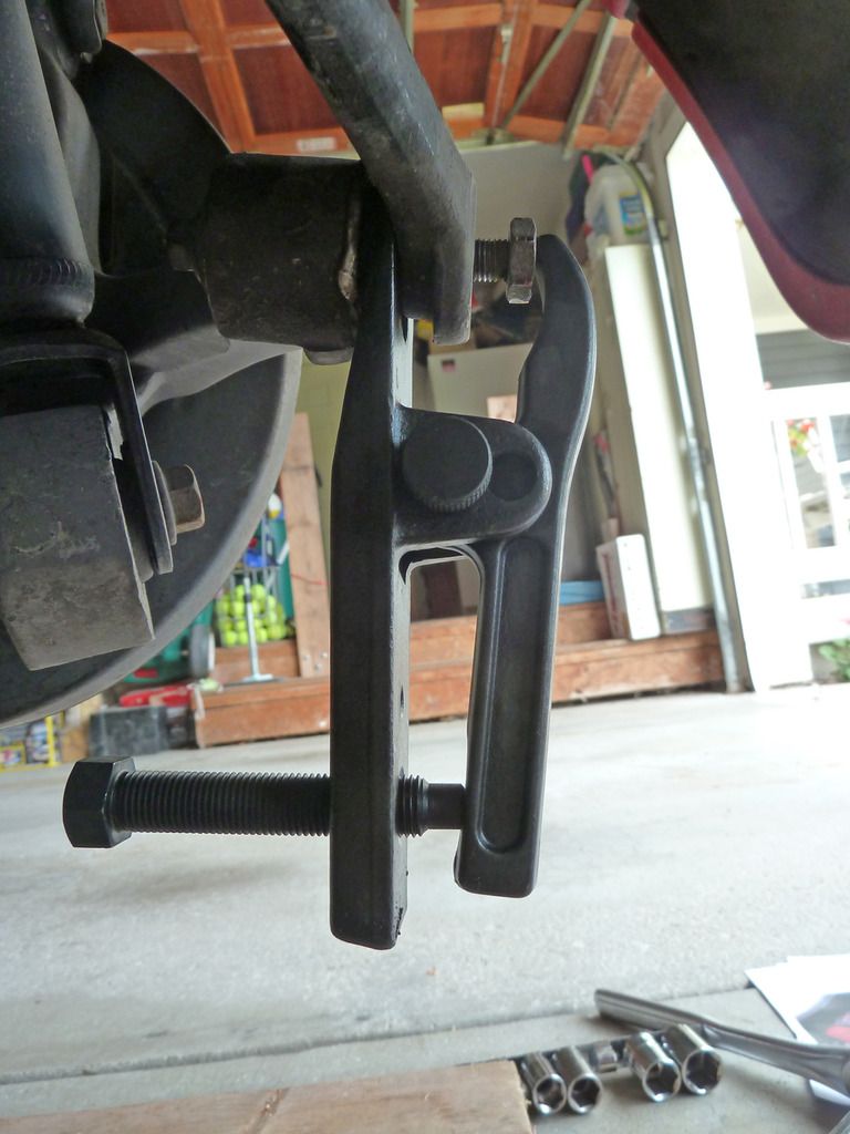
7. Proceed to tighten down with 3/4 socket and ratchet. It doesn't take a lot of effort. (right tool for right job!) After a minute or so it will suddenly break loose with a LOUD bang so don't be surprised by it. :-) This is normal. 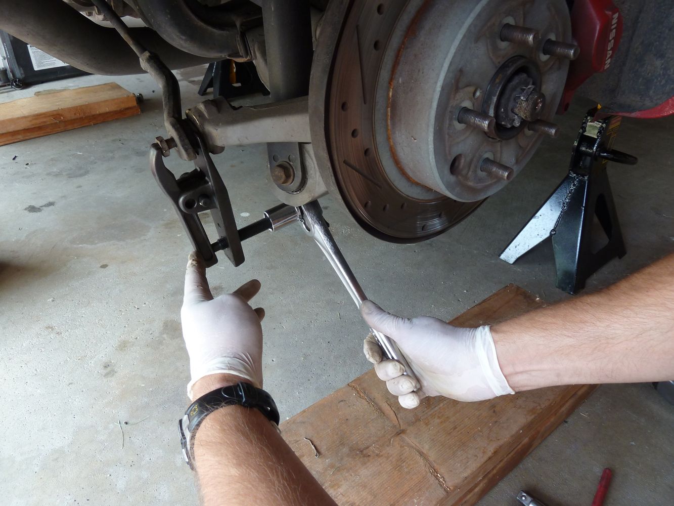
End link popped off from joint. 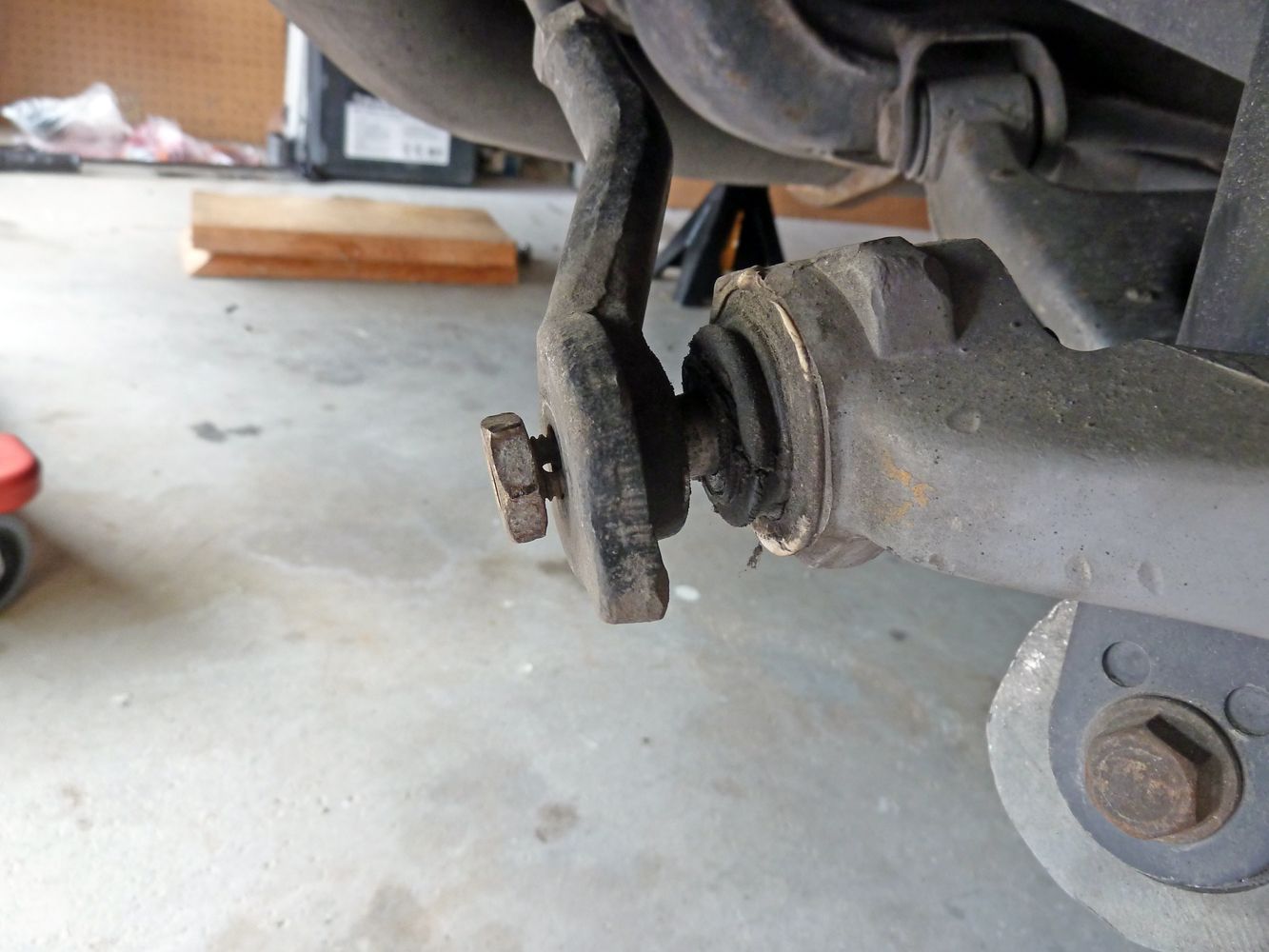
8. Remove the nut and slip off the tie rod from the joint. At this point you have two options. You can either continue with the ball joint removal process, or move on to the less time-consuming inner tie rod replacement. I chose to replace the tie rods before tackling the ball joint removal. Replacing the HICAS inner tie rods 9. Hold inner tie rod with vice grips to assist in loosening the 19 mm Jam nut. Loosen the Jam nut then unscrew outer link while counting the number of full rotations of the "face" of the end link. The face is the part that faces the ball joint. Write it down for each side. This will help you install it back in approximately the same alignment location, but regardless, you WILL need to get an alignment after performing this procedure. Also I have read where others have also counted the number of exposed threads on the inner tie rod too. I didn't find this to be much help and only referred to the removal rotation numbers when reinstalling, and even then I had to fudge a rotation of two to get the end link back on afterwards. Hence, the need to get an alignment done. The pic below shows where the vice grips go. In this pic I've already loosened the jam nut to the left of it. 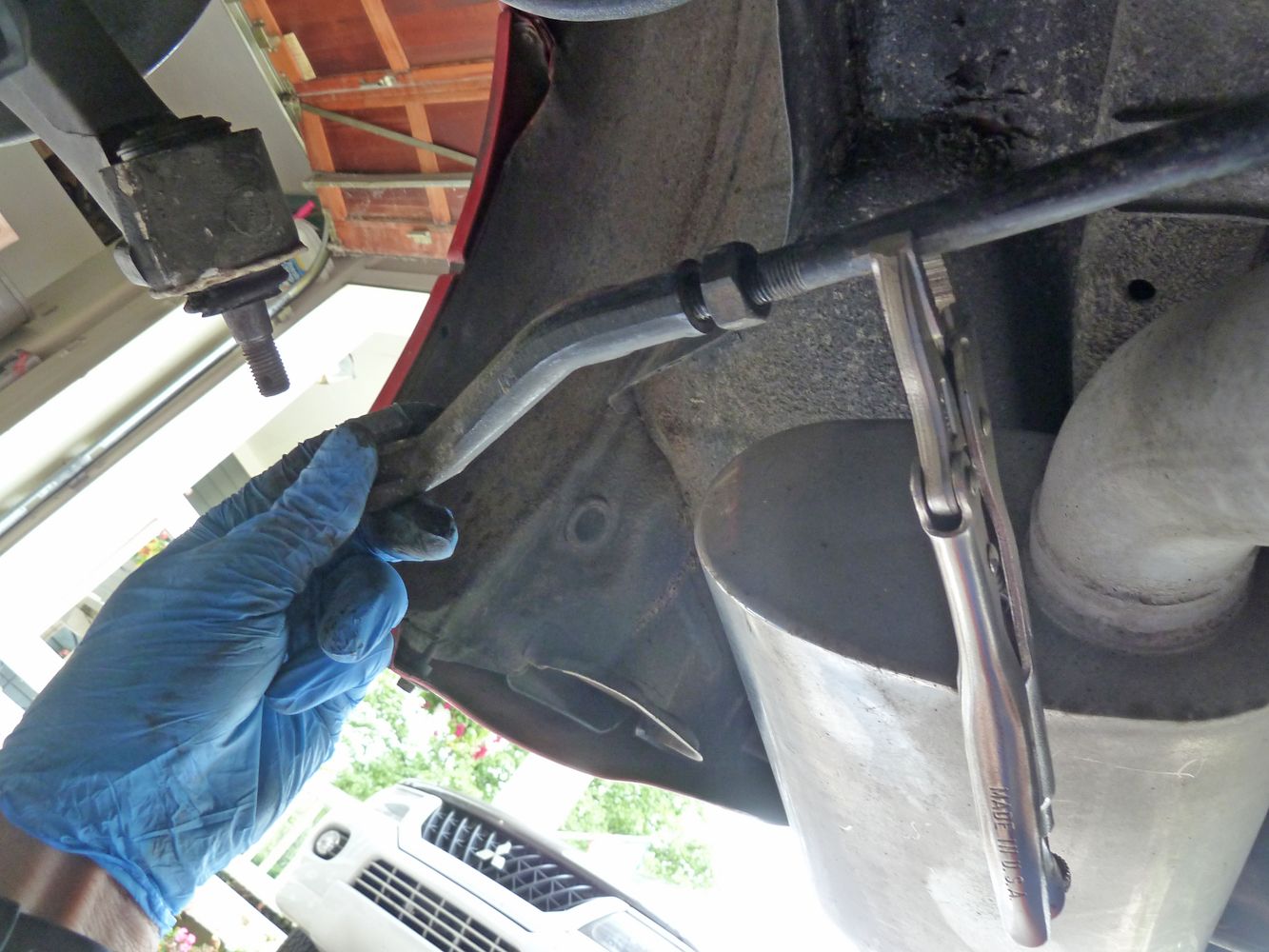
10. Next, remove the tie rod dust boot by untwisting the wire. Use a small screw driver to pry around the smaller end of the boot and loosen it. If it stll has the small rubber band on it, cut it off. Wriggle and twist the boot back off the joint of the tie rod towards the wheel hub. It will want to bunch up near the small end. Spray a little lubricant on the tie rod and it will help it slide back off. 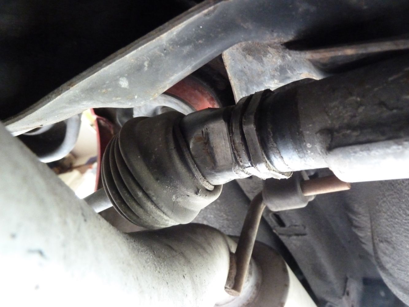
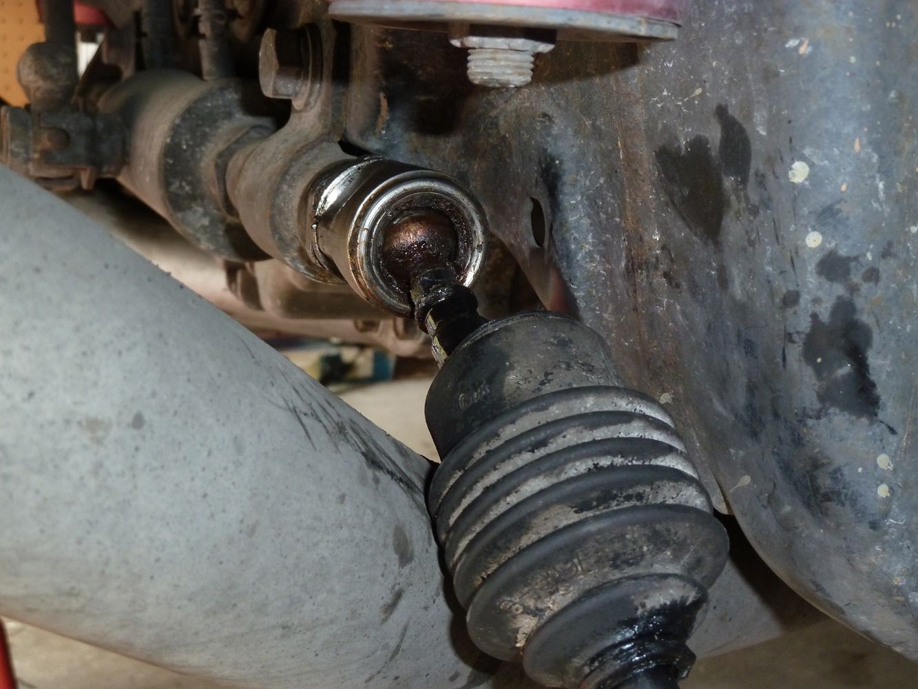
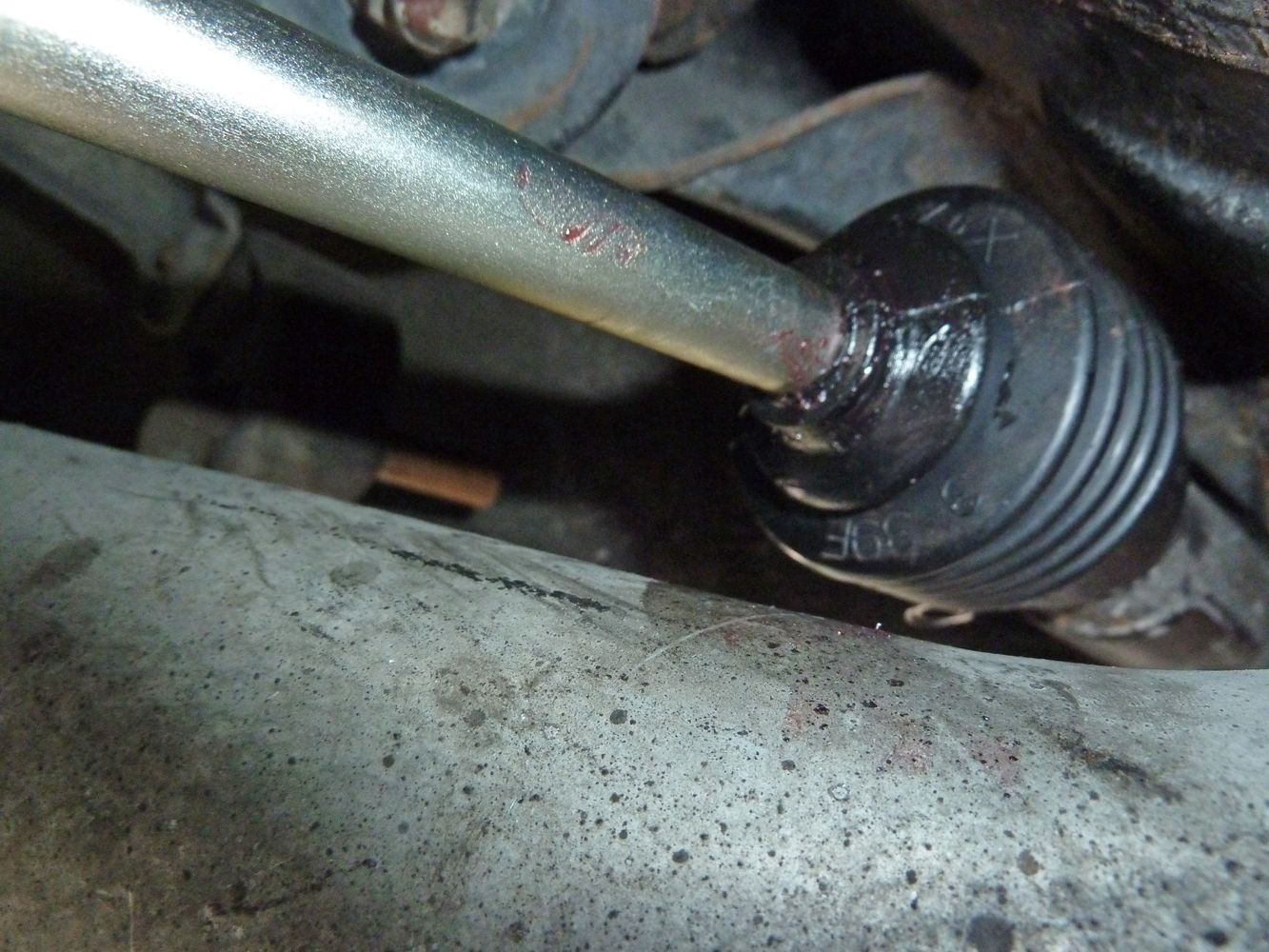
Here's a look at the old tie rod joint. Man, was it ever loose. No resistance at all to move it around. The new one had MUCH more resistance.
 11. Next you will need to use your 32 mm wrench and crescent wrench to break free either one of the tie rods. It takes a good amount of torque so I slipped the 1 1/4 pipe over the end of my crescent wrench to get it. Put the wrenches on the square part of each tie rod. Hold one side steady and rotate counter-clockwise the other one until it breaks free. If it's particularly tough you may need your assistant to brace the stationary one. (Note: I have a Specialty Z X pipe exhaust and I had plenty of space to access the tie rods without removing it. However if you have a different style exhaust you may have to remove the mufflers to get access to the joints under the boots.) 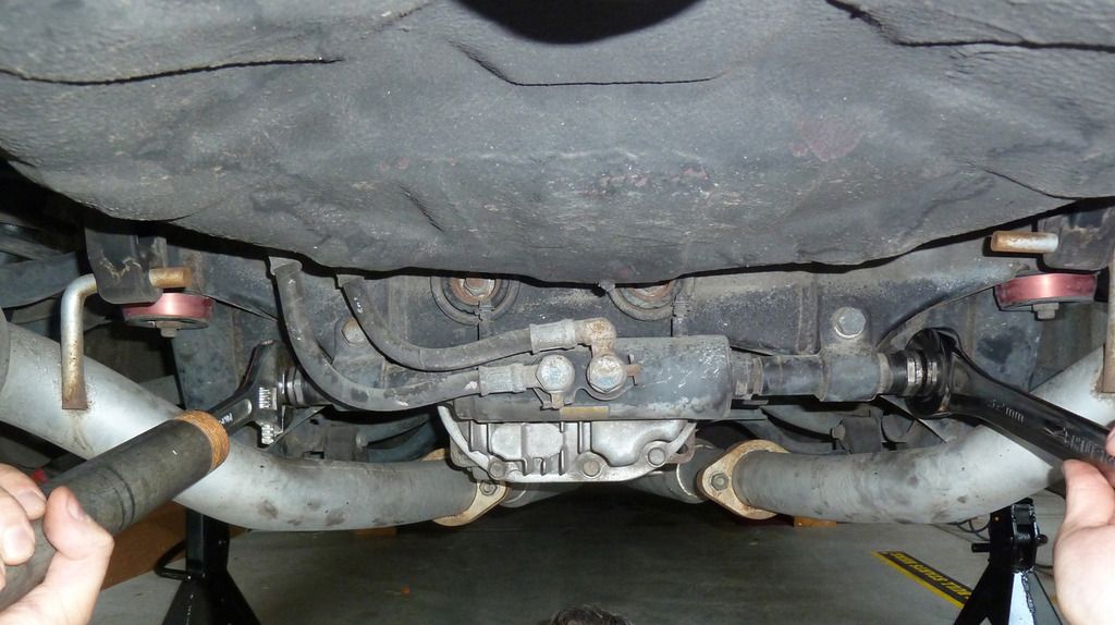
12. The tie rod that breaks free will be tie rod #1. The one that did not will be tie rod #2. Unscrew tie rod #1 from the stroke stopper which is shown below. 13. Use your large 38mm crescent on the edge of the Stroke Stopper to loosen it. With such a big wrench it takes very little effort to break it free. Then unscrew the rest of the way with your fingers. The inner edge is a lock nut. Try not to change this position relative to the outside edge when unscrewing. 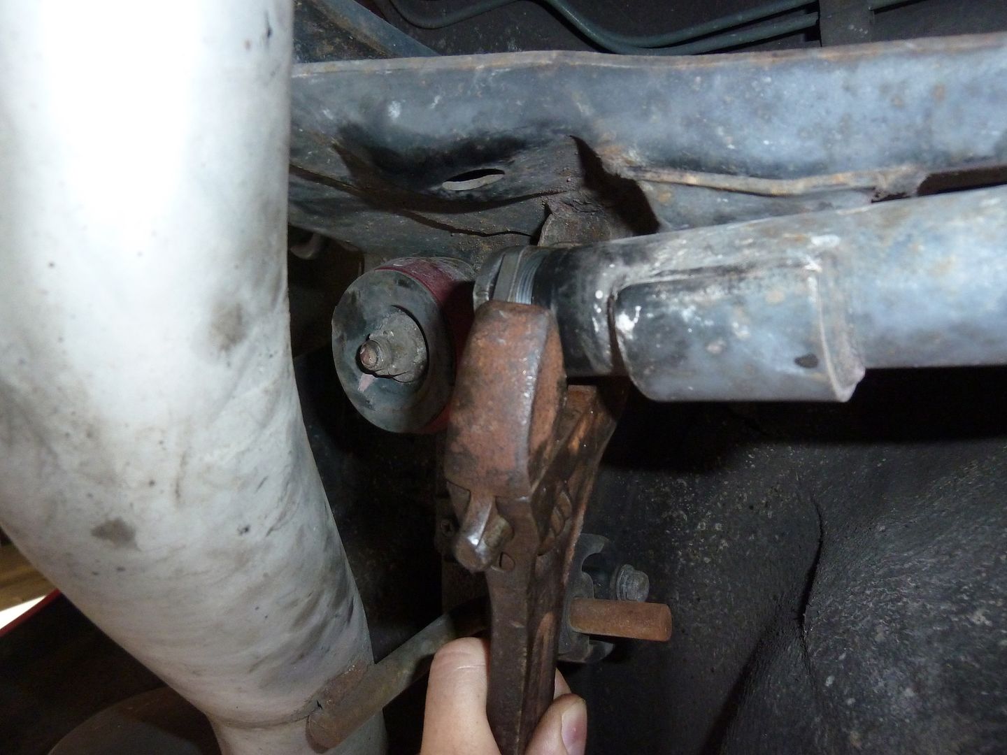
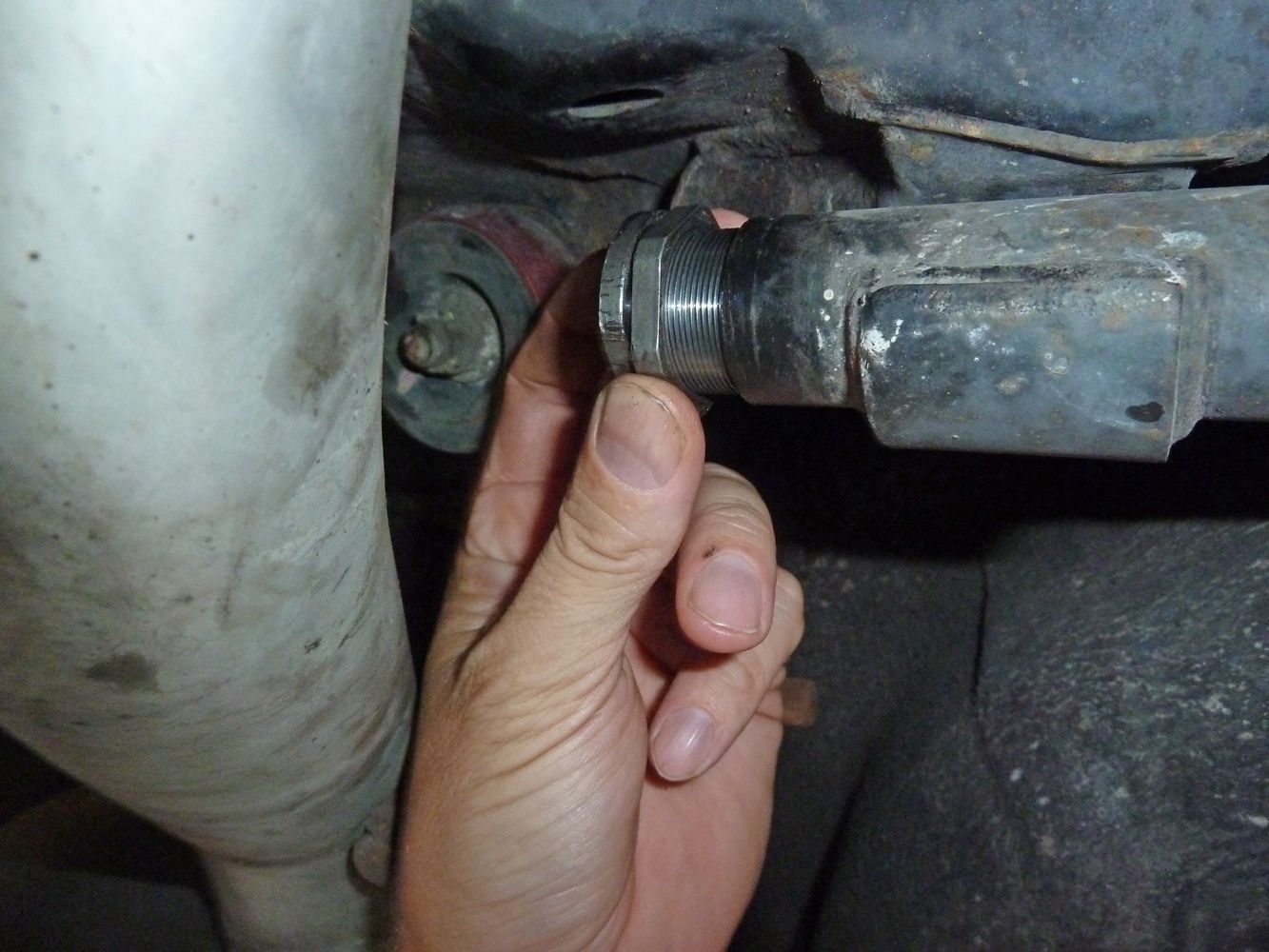
14. What you will be left with is a 17 mm beveled edge cylinder that the tie rod screwed into. You will put your 17 mm wrench with a pipe on the end of it to hold it in place while you use your 32 mm wrench on tie rod #2 to break it free. Once again, you may need an assistant to hold the 17 mm in place while you break the other side free. Be sure you have the 17 mm wrench positioned on the flat edge of the cylinder. 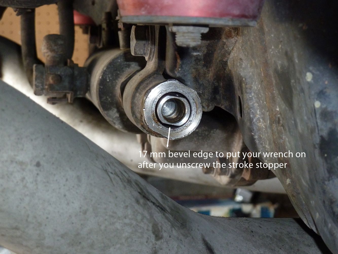
15. Transfer the boots and jam nuts to your new tie rods or put on new ones if you bought them like I did. If you've bought aftermarket tie rods, compare them to the ones you removed to note any differences in length or threads or jam nut size. The one on the right is an SPD tie rod ~$40, the OEM one was ~$70. Only difference I noticed was that the flat part on the tie rod end seemed to be ever so slightly narrower but it wasn't a problem. It also came with a thinner jam nut so I chose to reuse my older jam nut so I didn't have to account for the difference in width when counting the number of threads to install it. 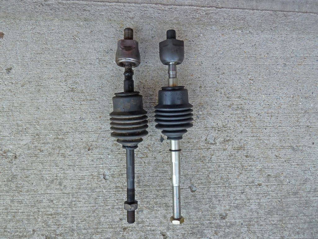
16. To make it easier later, slide the boot on as far as you can without covering the part of the joint you will need to put your wrench on later. Coat the joint end of tie rod #2 with Blue thread locker. Screw the tie rod into the HICAS power cylinder so all the threads are fully in hand tight. You'll have to use the 17 mm wrench to hold the other side while doing this. Don't worry about getting it super tight right now. 17. Re-install the stroke stopper on the other side and tighten with the 38 mm crescent wrench. Manual says between 38 to 51lbs, so a bit more than hand tight should do it using the wrench and pipe. If you've inadvertently moved the lock nut on the stroke stopper, use the spacing on the other side as your guide and make sure you tighten it back to the same space. Pages ST-48, ST-51, and ST-52 in the service manual show all the torque values and exploded view of the tie rods and stroke stopper parts if you need more reference. 18. Repeat step 16 for tie rod #1, don't forget the Blue thread locker. 19. Next, use your 32 mm wrench and crescent wrench with pipe on the end of it to tighten the tie rods against each other like you did in step12 to break them free. Tighten them as hand tight as you can. 20. Slide boots fully on and put on your new wire. If reusing your old boots you can use new wire or zip ties. Apply a bit of grease to the outside of the small end of the boot. Then slide the small rubber band over it. 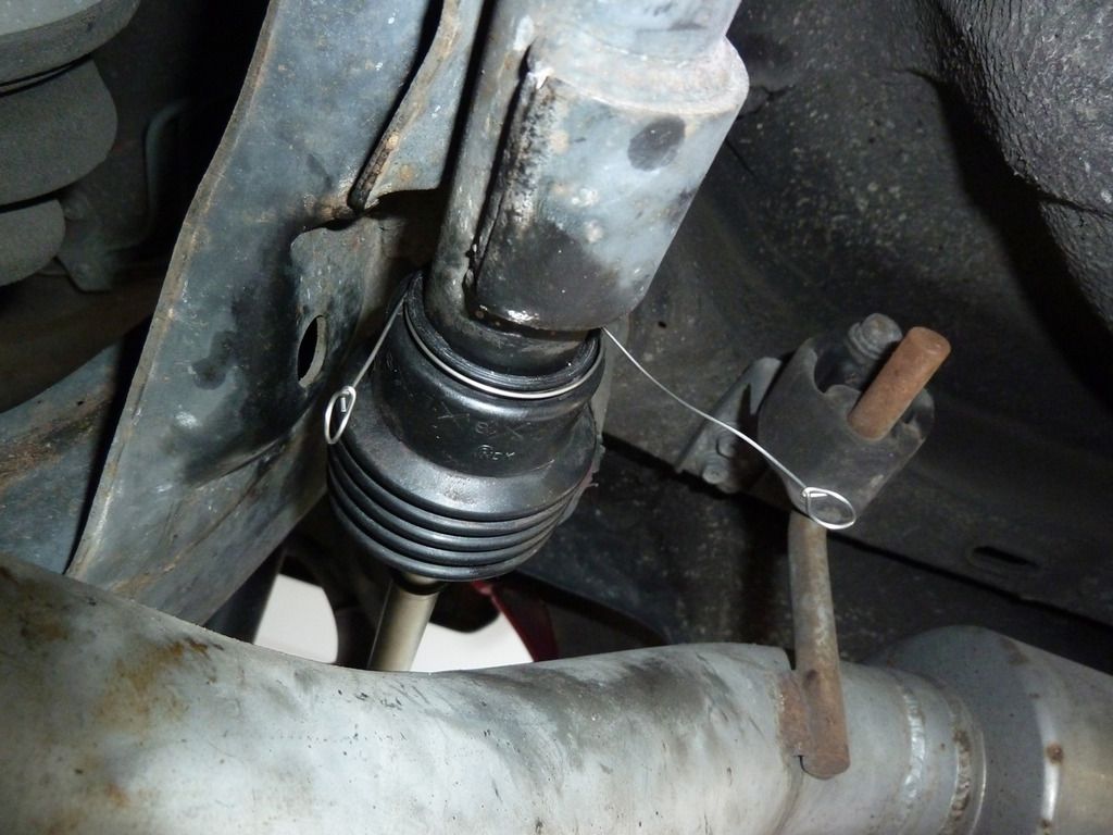
21. Apply anti-seize to the jam nuts and screw on the tie rods. Then install the tie rod end links. Start with the face of each facing the ball joint and rotate the rod on the number of rotations you recorded earlier. 22 A) If you are using your existing ball joints then slip the end links over the bolts and tighten the jam nut. You will likely have to fudge a bit on the rotation or nudge the angle of the ball joint bolt to get the end link to fit back over the bolt. Once you get it lined up tap it with your rubber mallet to press it on enough to get the nut screwed on. Tighten to 33 to 44 lbs and then insert the cotter pin. Lower the car and then tighten the jam nuts once more when the wheels are supporting the weight of the car. Go get a 4 wheel alignment as soon as possible. 22 B) If you are replacing and pressing in new ball joints, proceed to the next section. Replacing the rear HICAS ball joints 23. Spray the edges of both joints with lubricant now so it has a little time to work into the crevices. 24. To make room for the ball joint press tool, the struts need to be removed. Remove interior trim pieces in the trunk to expose strut bolts. This will involve using the 10 mm nut driver or socket for the trim pieces, phillips head screwdriver and other sockets and extension for the 5 interior strut bolts shown below. Remove the two 8 mm actuator bolts, two 12 mm mounting bolts, and one 14 mm bracket bolt. NA's won't have the shock actuator. Once you have the actuator nut removed you will notice one side of the strut bolt is flat. Take note of which way it's facing and the way the bracket ears are facing. You will need to re-install both so they are facing the same way. 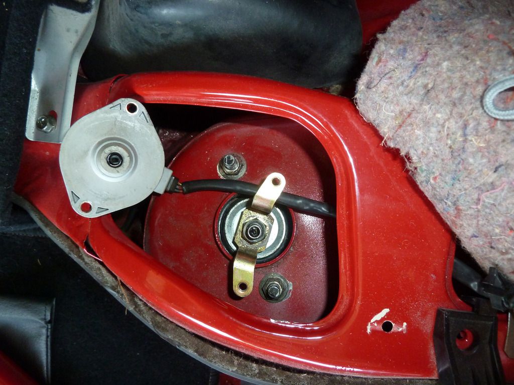
25. Move to the bottom of the car and use your 17 mm socket/ratchet and breaker bar, and your wrench to remove the bottom strut nut and bolt. 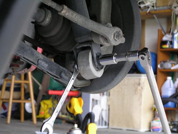
26. Now you'll want to get your assistant to help you prop the wheel down so you can remove the strut. Use the 15" piece of wood as the prop and the shorter piece as the base on the hub. Position it appropriately, taking care not to position your base as to impede the removal of the strut. Stand/bounce on the hub to force it down while you or your helper can force the prop in place. When this happens the strut will drop down. 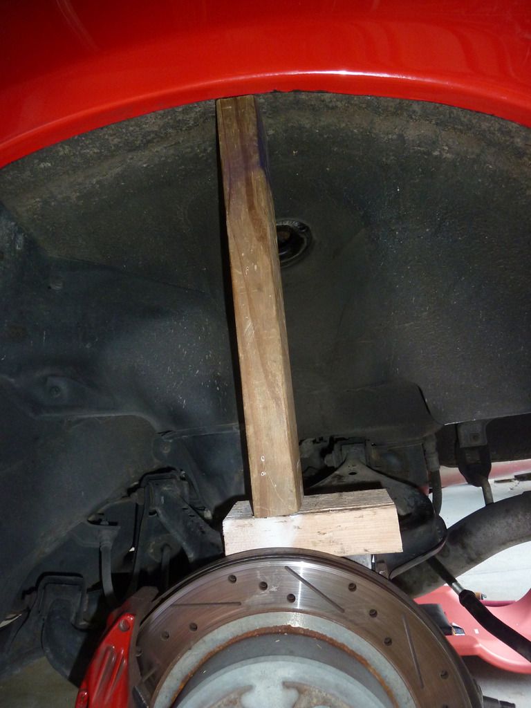
27. Use the rubber mallet or strike the strut with your hand a few times to pull/knock it loose from the strut bushing. Maneuver it and the strut spring assembly down, then at an angle and back up over the control arm and out of the wheel well. You'll re-insert it in the wheel well at the same angle when you re-install it so try to remember it to save time. 28. Now you will need to assemble the press tool and the adapters as shown. It helps to have a helper to hold things in place while you tighten the press. Pressing out the joint takes 2- 3 different set ups because as the joint begins being pressed out you have to keep adding a nut/socket to the non-screw side to increase your pressing distance. The first step is to affix the thin flat adapter (shown at right in pic) and then tighten the press until it is flush with the hub. 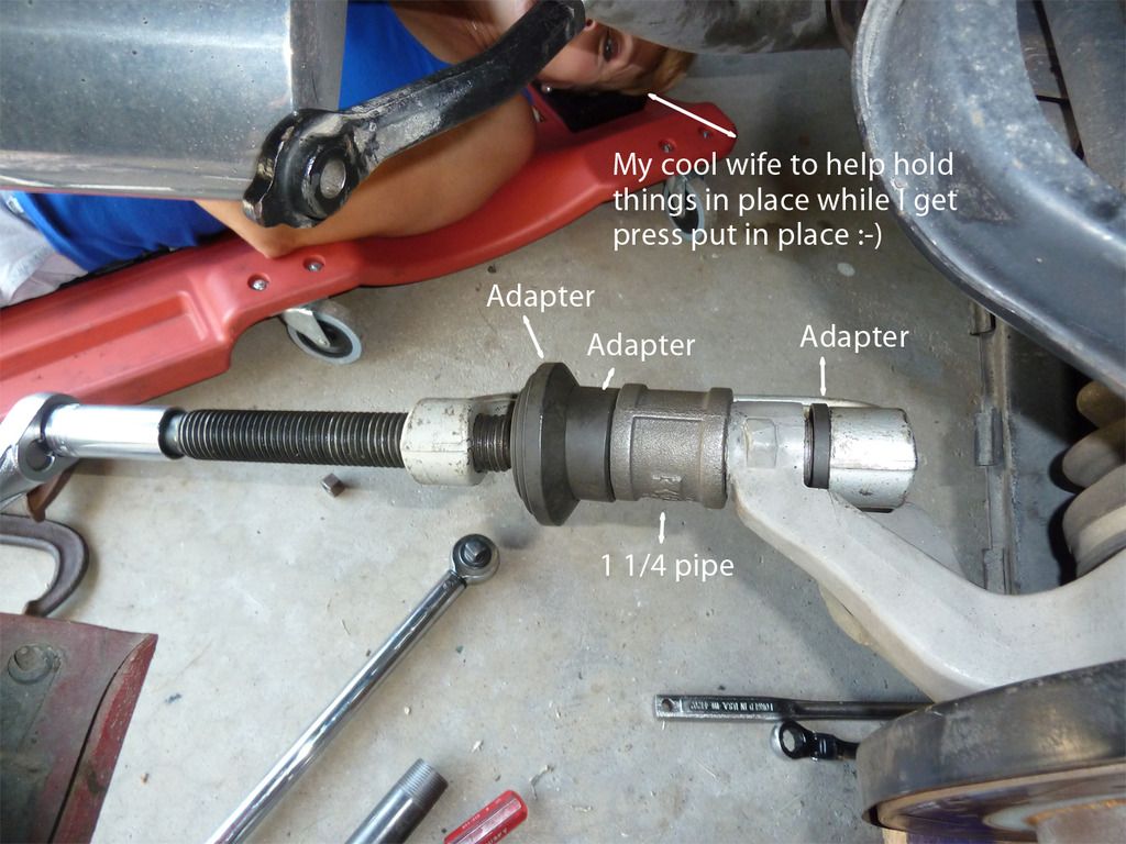
Note you need to initially let the press rotate to wedge against the hub so it doesn't turn when pressing. 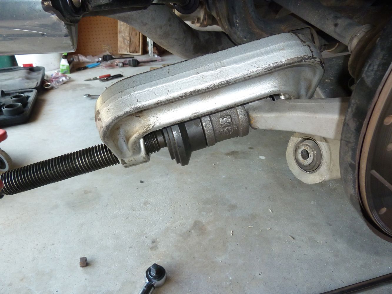
The adapter on the left in the pic above has a recessed area that holds the screw so it doesn't torque off when turning. Something a regular C-clamp doesn't have and it makes a huge difference in applying the pressing force where you want it. 29. Once you've got it in place use your 7/8" socket and breaker bar with the pipe on the end for additional leverage and begin tightening. Slow and steady wins the race. It takes some effort but nothing too tough, what takes time is having to reposition the socket on the breaker bar after each turn. I stood and rotated the breaker bar up and down like I was jacking up a car and that seemed to work well. This is why it's important to have the car jacked high enough to have room for the breaker bar and pipe to rotate enough without hitting the floor. The first several turns wiIl require the most effort since the joint still has the largest surface area contacting the hub, but once it starts moving it gradually gets progressively easier. Spray a little lubricant every so often between steps. Still, the entire joint from adapter set up to press out only took about 15 minutes. It was a humid 93° when I did it so I did have a sweat worked up afterwards, but I think that was more from the sauna-like temperature and not the effort. Your climate/time to complete task may vary. :-) I got smart on the second joint and started taping the pieces in place which made it easier for me and my helper to quickly line them up. Note there is a 5/32" socket taped on the press tool in this pic. In hindsight, I could have probably started with this set up. I chose this socket size because it was the right diameter and length to fit in the space. Not too wide or too long. 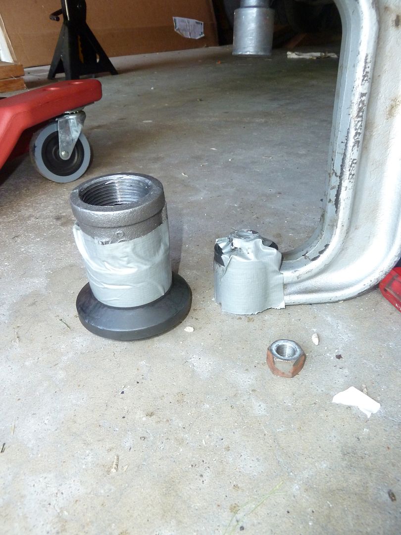
30. Once you've got the joint pressed out, clean up and scrape off any old sealant or gasket residue from the hub surface. Spray some lubricant on the new joint and insert into the hub. Remove the rubber boot so it does not get damaged when pressing in the new joint. You will put this back on later. 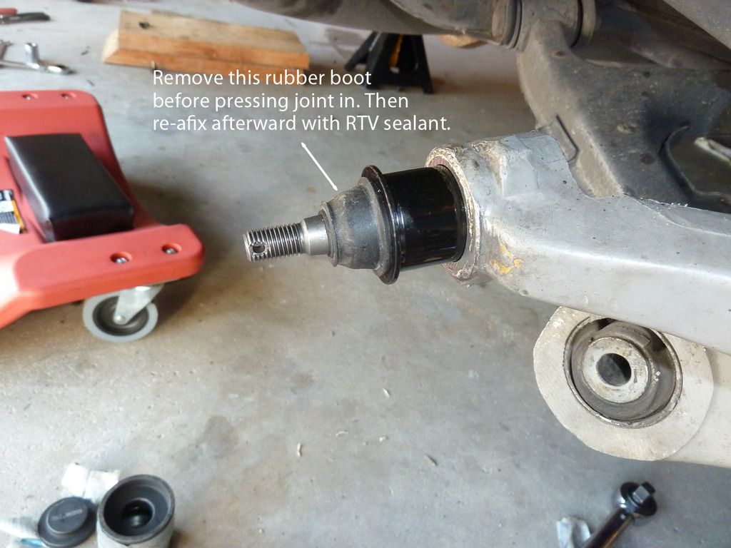
31. Affix the two adapters so that they mate together and the bolt of the joint has room to protrude through them. Tighten the screw and press in the joint until the lip of it is flush with the hub. It takes even less effort to press it in, about 10 minutes, and no stopping to change adapters or adjust the socket because you can use a ratchet instead of the breaker bar. 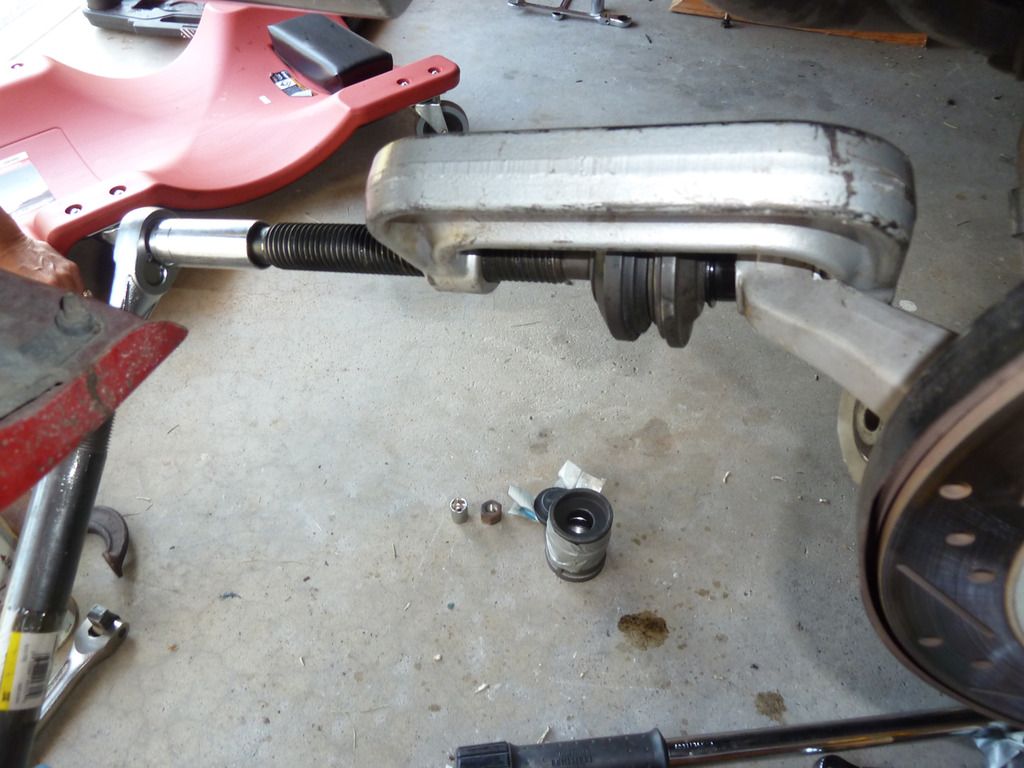
32. Replace the dust boot by applying black RTV sealant/gasket maker to the boot and pressing it back in place on the joint. Let it set up for at least a 1/2 hour before you put the end link back over it. While this is setting up move over and remove the second ball joint. 33. After replacing both joints and allowing time for the sealant to set up, slip the end links over the bolts and tighten the jam nut as directed in step 22A. 34. Re-install struts, make sure flat side of strut bolt is facing same direction as when you took it out. Line up upper bolts and insert in holes, then use rubber mallet to nudge strut roughly into place at lower bolt hole. 35. While you loosely hold spring assembly in alignment have your helper knock the strut board out of place using mallet or wrench so that bolts protrude through openings. To avoid injury do not use hand to knock the board out and keep fingers out of springs! 36. Align and insert lower strut bolt and push through and then hand tighten using wrench and ratchet before tightening upper strut and bracket bolts. If you push on the bolt while tightening it it helps the pointed end guide and align the bolt through until the threads emerge. Torque lower bolt to 72lbs. See the Strut installation write-up if you need more detail in installing them. 37. Install wheels and torque lug nuts to 72 - 85 lbs. 38. Get a 4 wheel alignment as soon as possible. Until that is done the car will likely still feel loose in the back end. But after replacing these items and getting it aligned my car felt like a new car. So solid, took care of the loose back end and eliminated a long standing issue where my right rear tire would break-free earlier than my left on hard acceleration, that caused a slight fish tail. Yes, it is a tedious task, but I highly recommend doing it if you have noticed the car doesn't handle like it use to around corners or simply want to recapture that new car handling feel. Here's a recap of rough time frames it took me for various tasks: ~30 minutes for initial jacking prep, wheels removal/installation
~15 minutes to press out each joint
~10 minutes to press in each joint
~60 minutes for removal/install of tie rods
~45 minutes per strut for removal/installation including trim removal/installation Cheers,
doug8867
|


 Rear HICAS Inner Tie Rod & Ball Joint Removal /Installation -