Chipping the 300 ECU
I first started chopping away at electronics in the late 50’s as a kid.. usually ( always ) what I worked on did not survive.. But it was training for my life ahead. Fast foreword to a few years ago.. It was time to chip the NA 300.. as I like to do all work myself, I purchased a bunch of 300 ECU’s and went to work.. This is the technique that worked best.. There were others that had plusses and Minuses to them.. Getting the Circuit Board out of the case is a chore.. Need a NEW #2 Phillips Screwdriver and some ‘Brake Cleaner Spray’.. The Srews are locked into the Case with ‘Fingernail Polish’, and we need a solvent to loosen it up a bit.. Here is a shot of the Snout spraying a little on the Transistor Clamp Screws.. Spray a little, then wait a little.. DO NOT SCREW UP THE HEAD OF THE SCREW.. it will have to be drilled out if you do ( How do I know this ? ) 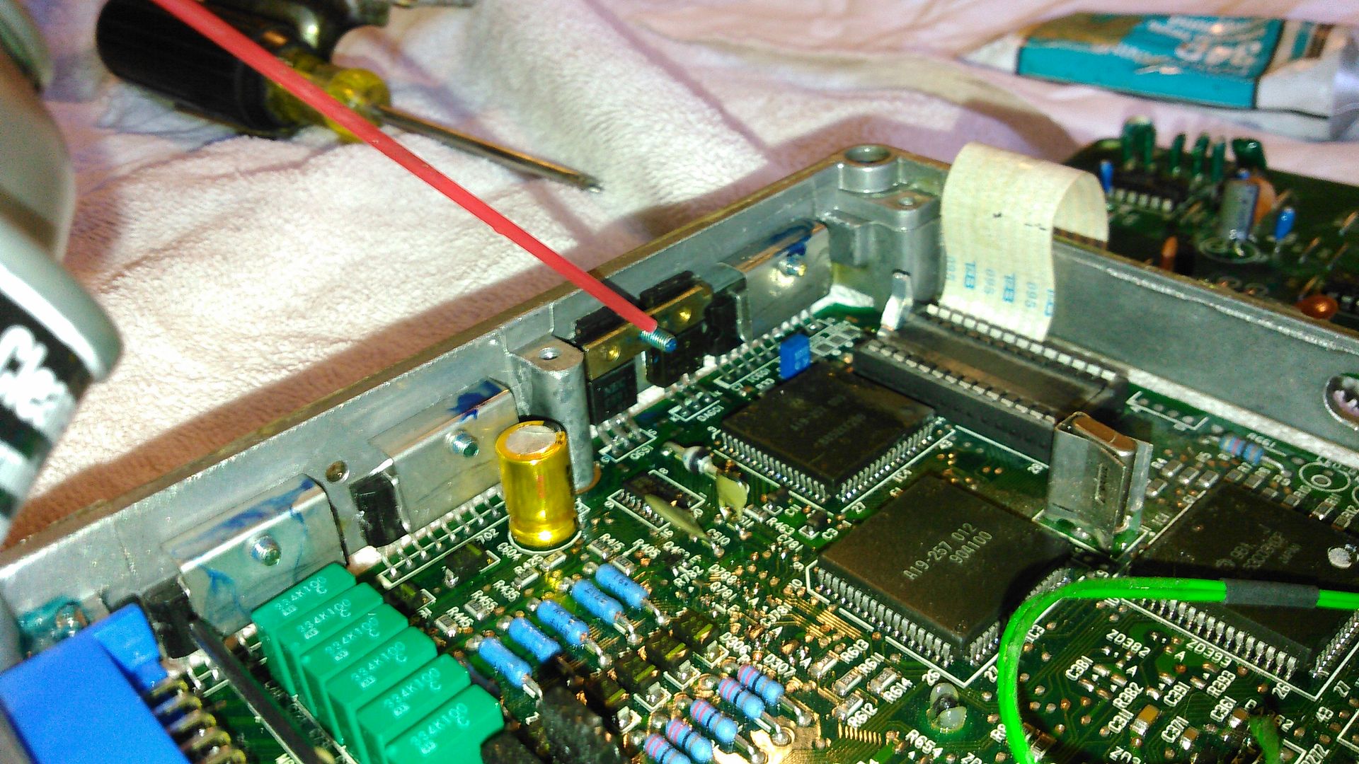
Also.. the Board has been painted with Varnish.. and this has glued the Transistors to the Side of the Case.. Spray a little Brake Cleaner on the transistor, and wiggle the transistor a little bit with a small knife.. if it resists, squirt again and wait a little.. It will all come loose, and then get all the screws out EXCEPT the one in the middle of the plug.. it is not necessary to remove..
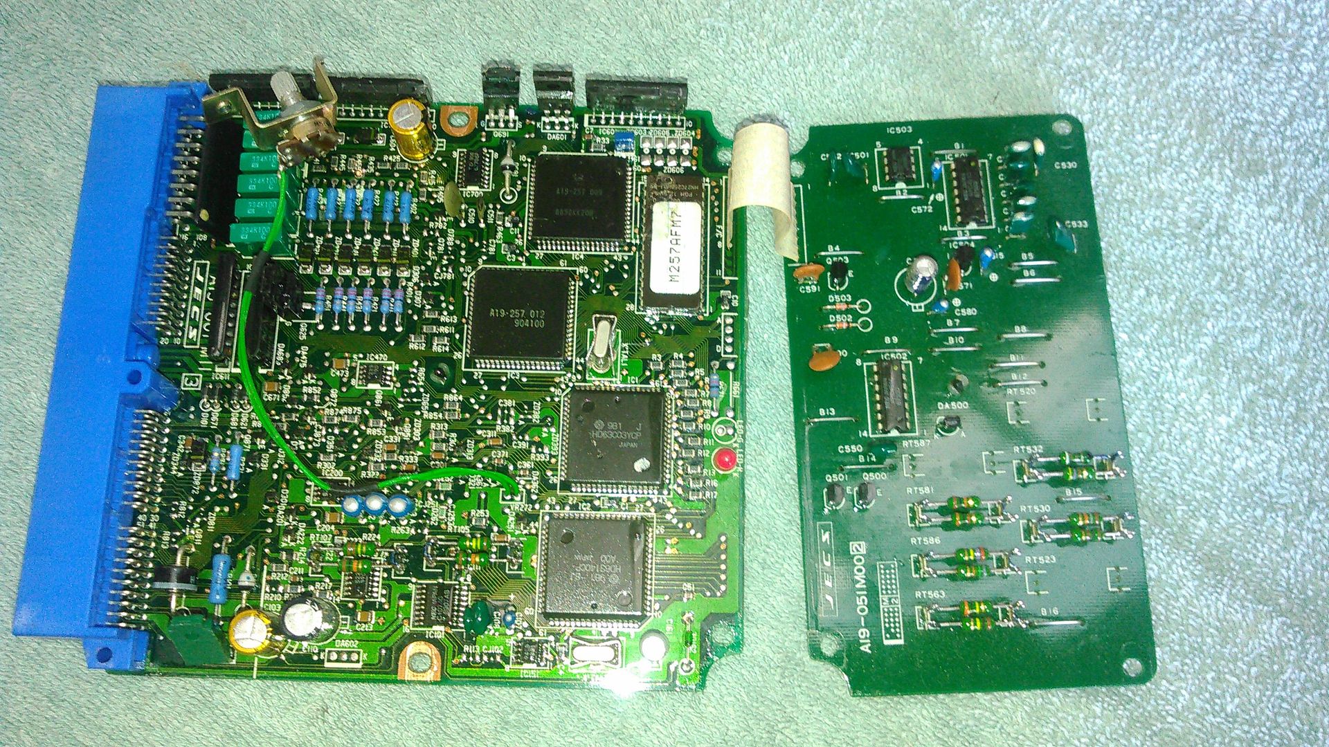
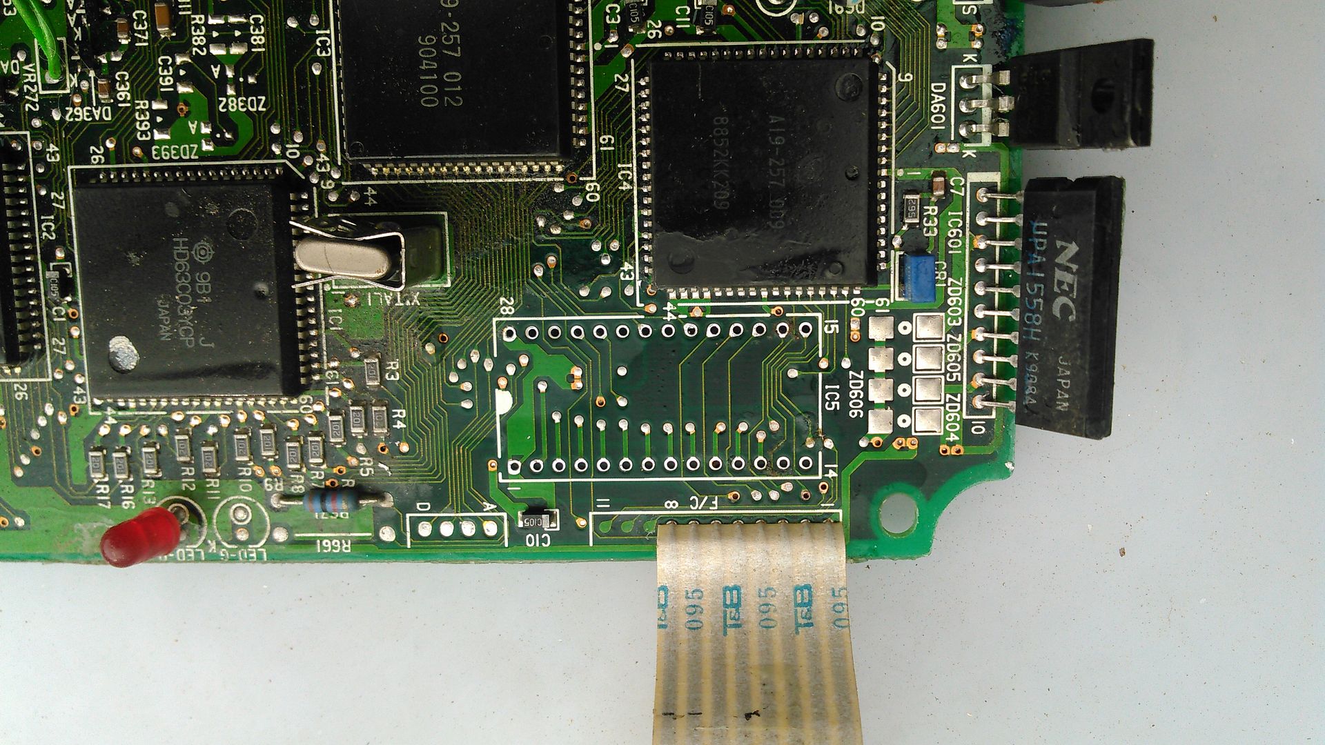
Here is an overview of the 8 Bit 90-93 300 ECU Guts..
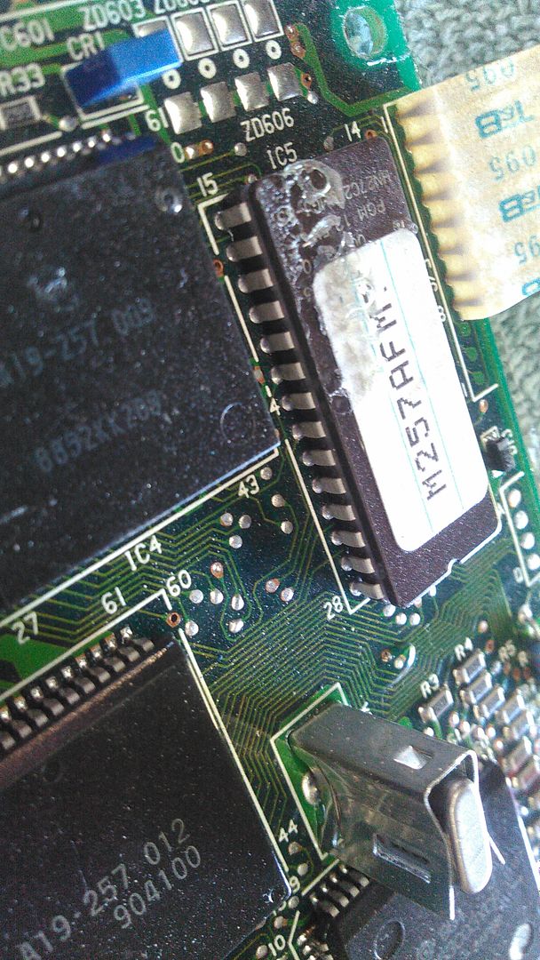
And this is a close up of ‘The Chip’..
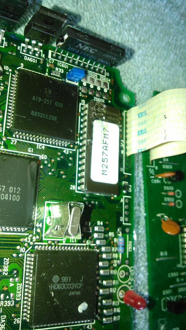
This is an Old School 28 pin Chip ( 70’s and 80’s Design ) that actually is a Light Erase Chip.. there is an Erase Window on the top that is covered by the label. The replacement chips are USUALLY an Electrically Erasable Chip.
The Chip needs to come out, and have a Socket re-soldered back to the Circuit Board, to allow quick replacement. The Problem is to get the chip off the board, and not hurt the Board.. the Chip will be Toast in this Technique.. I did develop two techniques to get the chip off intact.. not advised for the faint of heart.. First we have to Cut the Leggs of the Chip with a Dremel Slitting Cutter.
Here is the Dremel 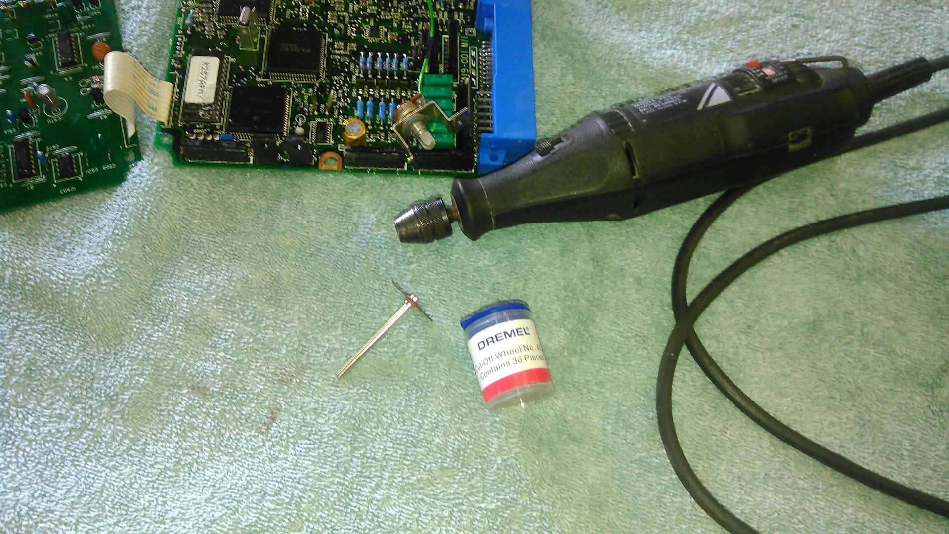
And this is the Chip uncut..
And this is in action.. 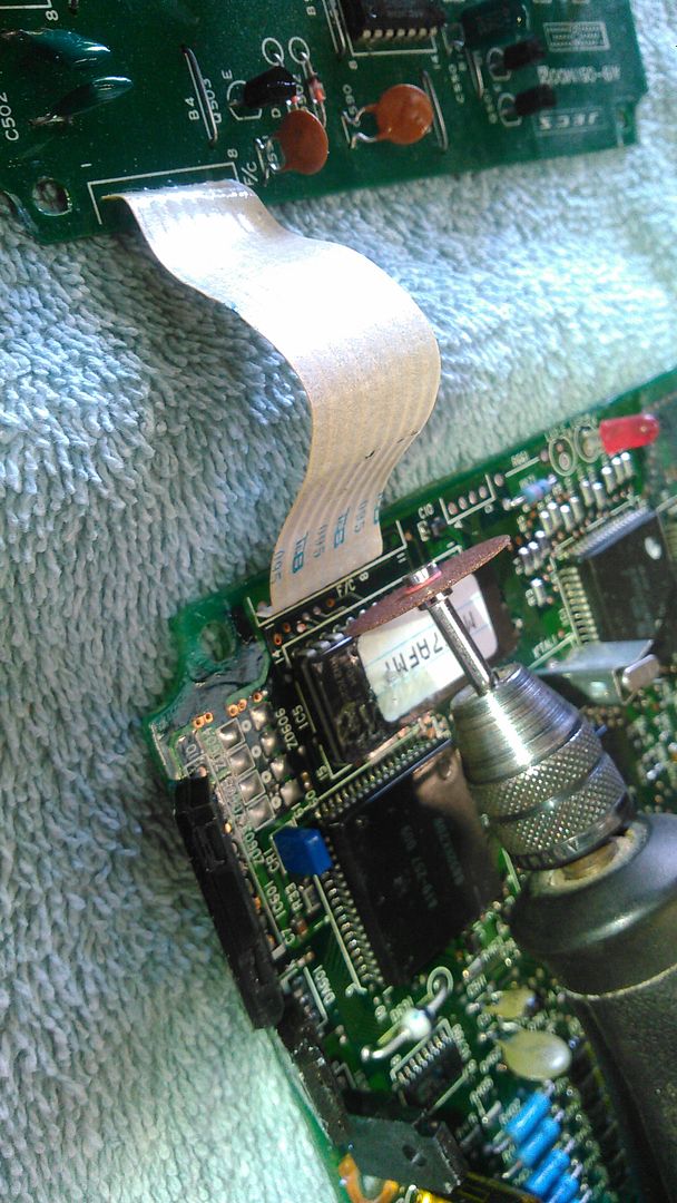
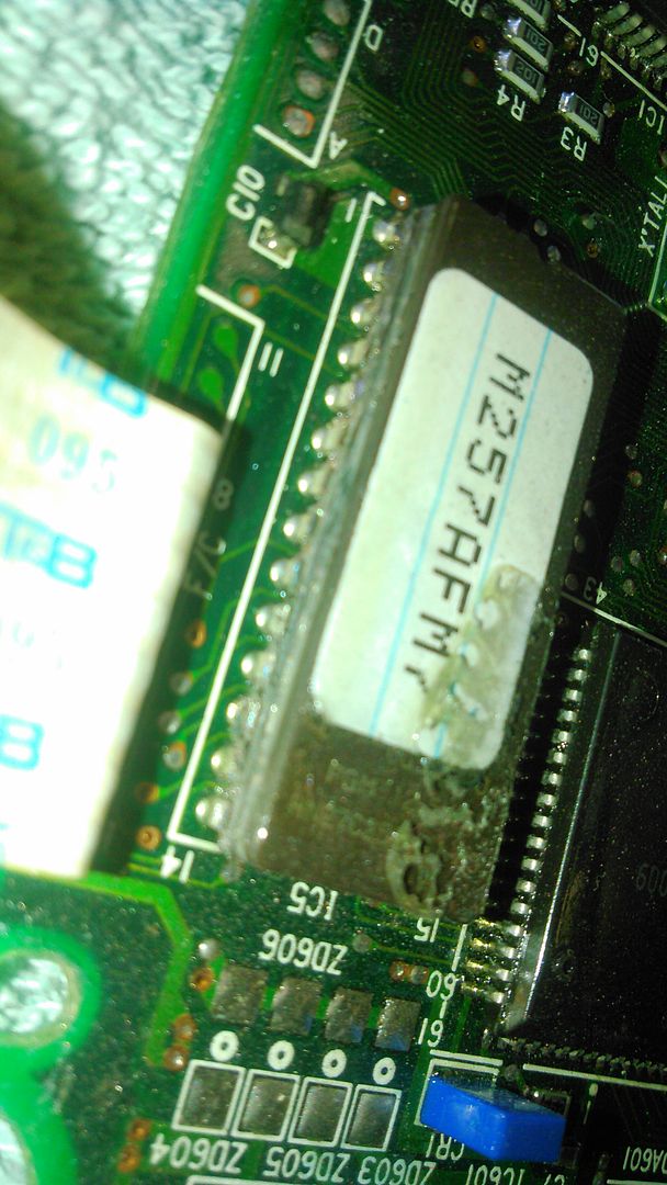
Here is a Close Up of the Side of the Chip.. You can see that the Legs DID come out of the seam of the upper half, and the lower half of the chip.. They have now been ‘Cut Through’ with the Dremel Slitter..
Now the problem is the Entire Board has been covered with a Lacquer.. This has glued the Chip down to the board.. we need to use ‘Brake Cleaner’ solvent to loosen the Lacquer to get the chip off.
Just use the Snout to squirt it under the Chip.. and wait about 5 minutes and squirt again.. it should lift off with a SMALL knife. 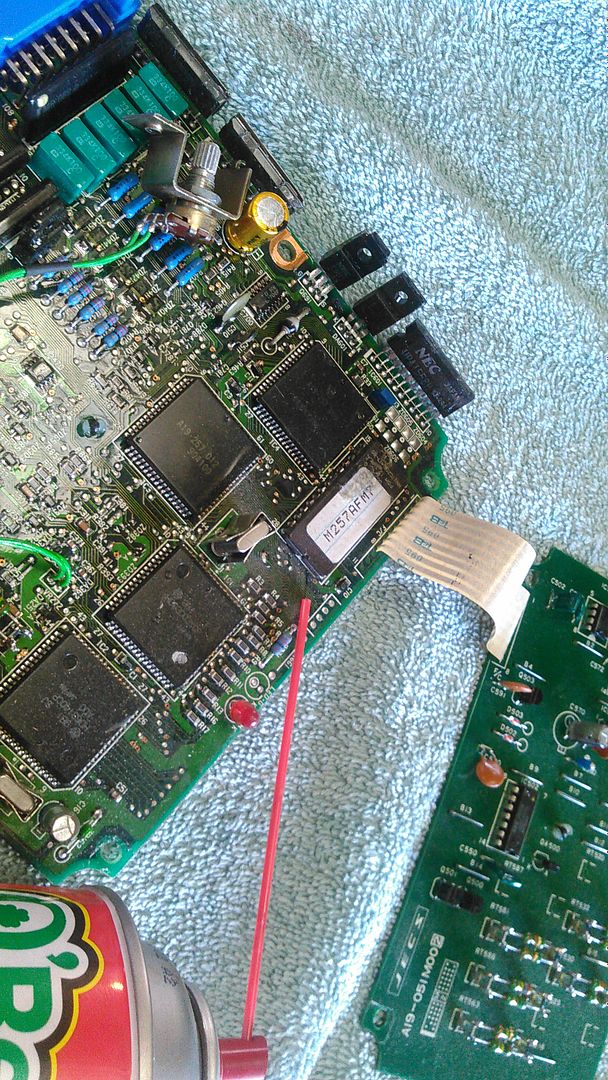
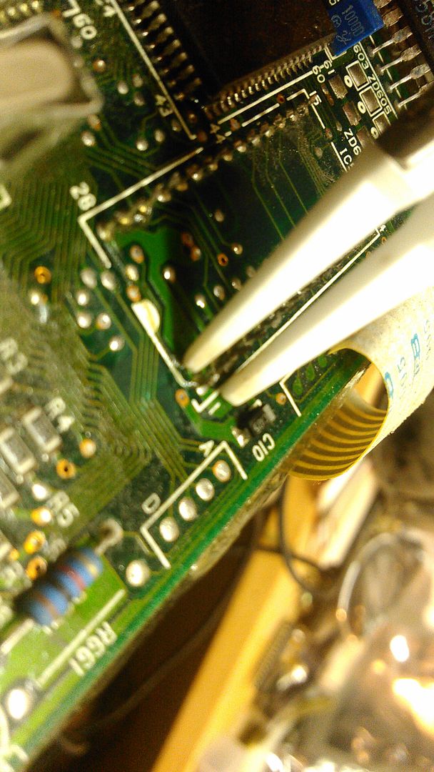
Here is it off the board.. 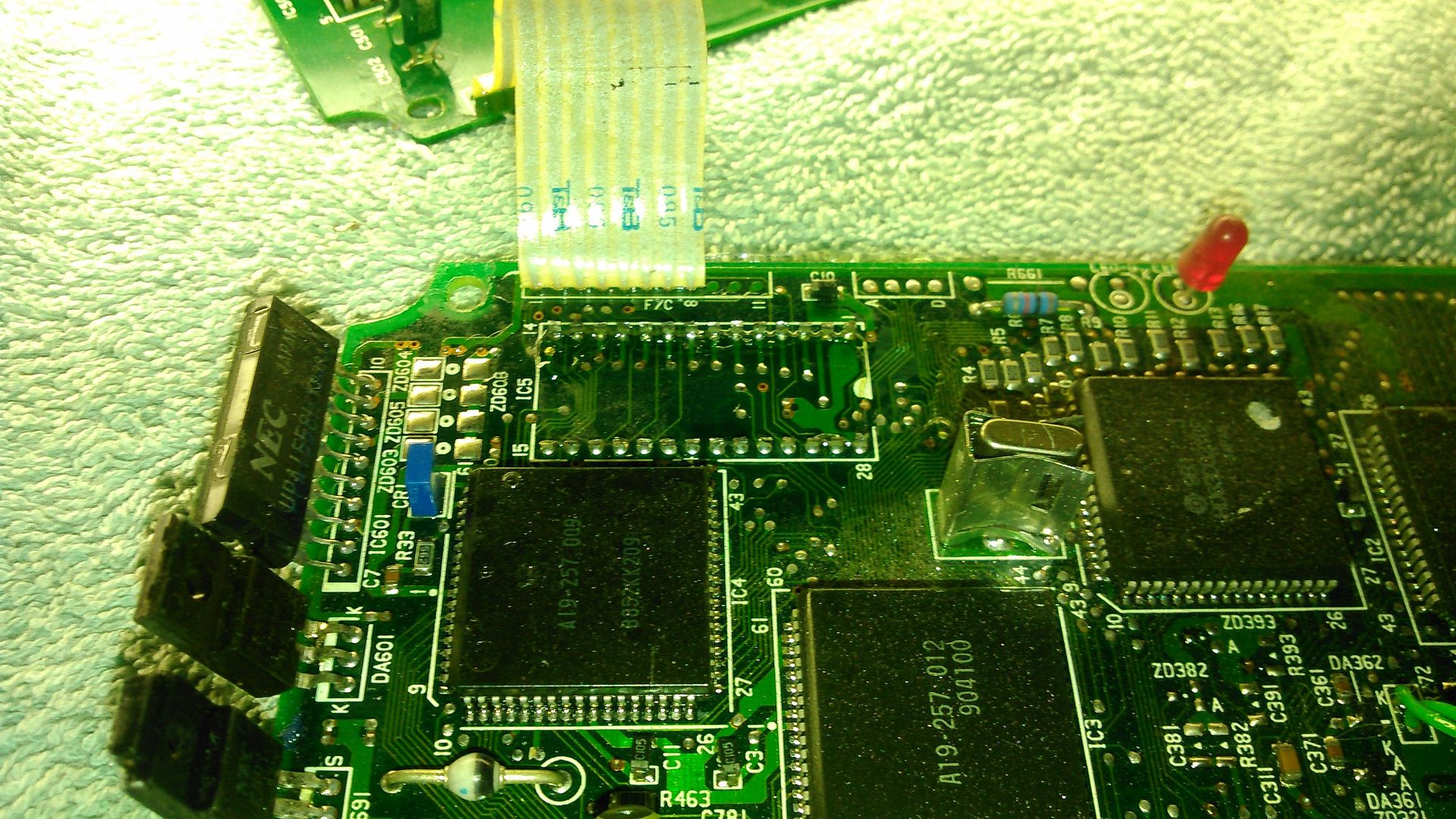
And a Close Up of the Chip Legs.. 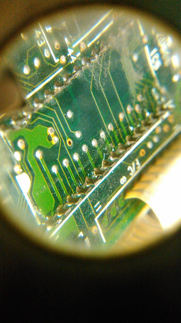
Now the real work.. The Leggs need to be removed from the board one at a time.. Solder Tip on one side.. 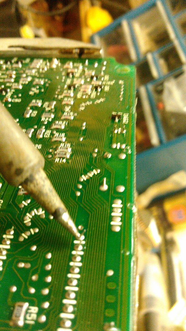
And tweezers on the other side..
Pin 1 and 24 are ‘CRAMMED’ into the board somehow.. and will be VERY difficult to remove.. I Suggest working on the others first, to get a feel and technique developed before you attack these last two pins for removal..
After Unsoldering the pins, it’s time to clean the Through Holes out.. 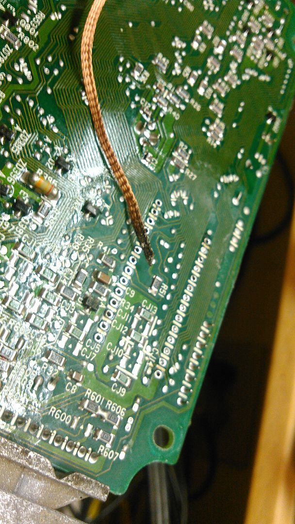
This material is ‘Solder Wick’.. it’s used to ‘Suck Up’ heated solder into it’s braided fibers..
Lay the Solder Wick on the Solder Pad, lay the Solder Tip on the Top of it, and the heated Solder will suck up into the braid..
Use Solder Flux to make things flow well.. After a first round of Solder Wick, the Board will look like this.. 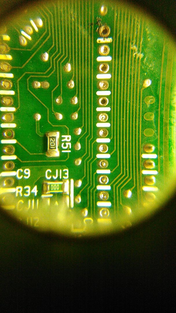
Some holes are open, some are still full.. Next round is to Cut the Solder Wick at an angle, and stick the Tip of the Cut Solder Wick and the Soldering Tip into the Hole, and heat it.. it will come out.. If you get a really stubborn hole, fill it back up with fresh solder and suck it all back out.. As you see on this one.. it finally all came out.. 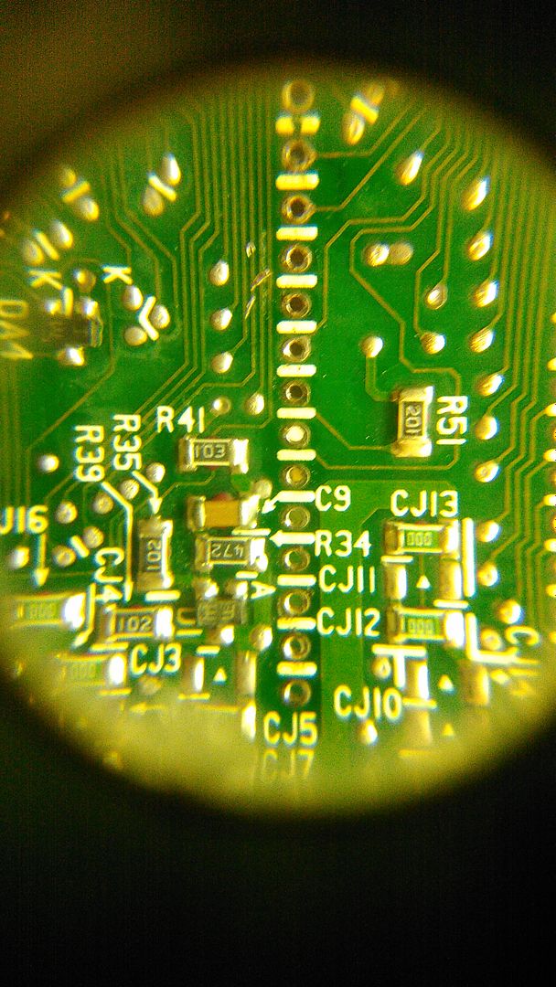
Now back to the Brake Cleaner Spray and squirt the board ( Chip Area ONLY ) and use a tooth brush to scrub the Gunk off the Board.. BOTH SIDES.. 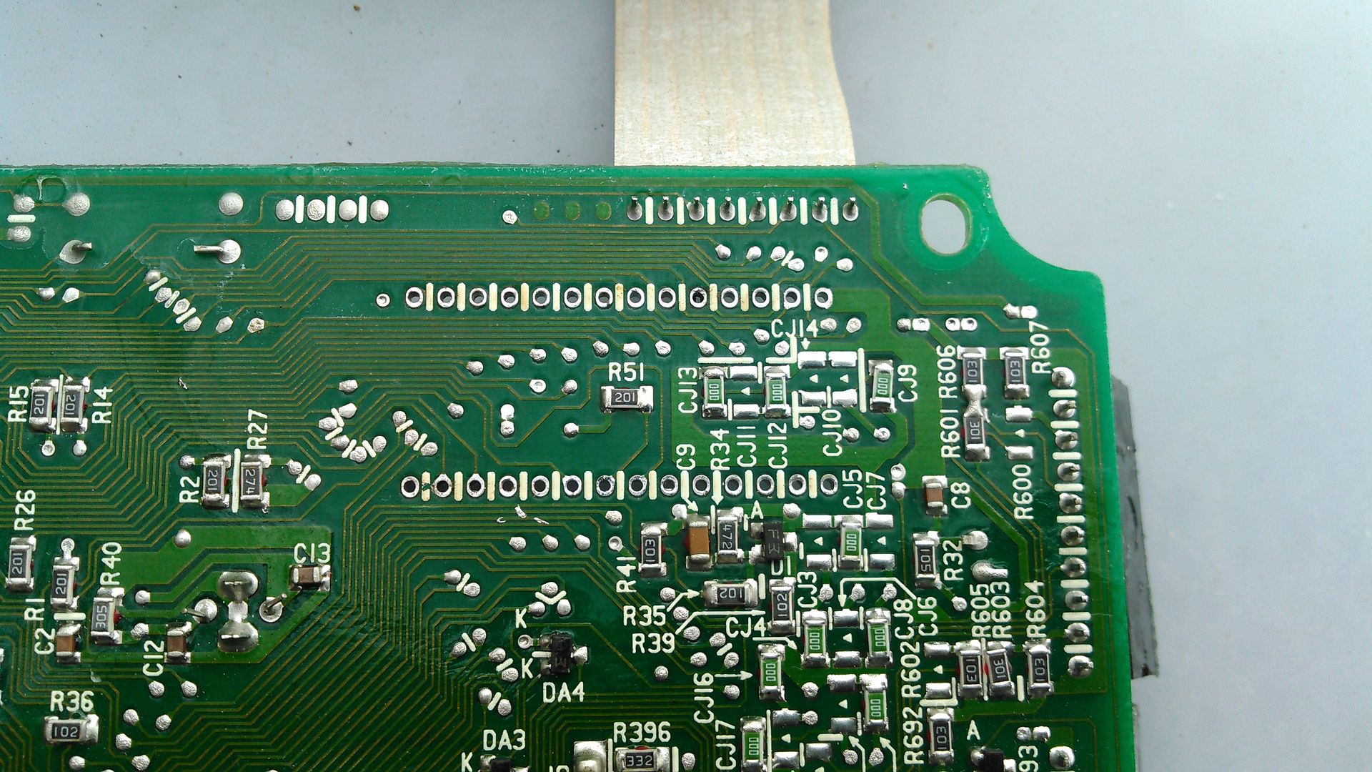
Now you are close to the end of the project.. Install the Sockett, and Solder into place.. This is a zif Socket.. zero insertion force socket.. it has an ‘Arm’ that will clamp down on the Chip Legs.. 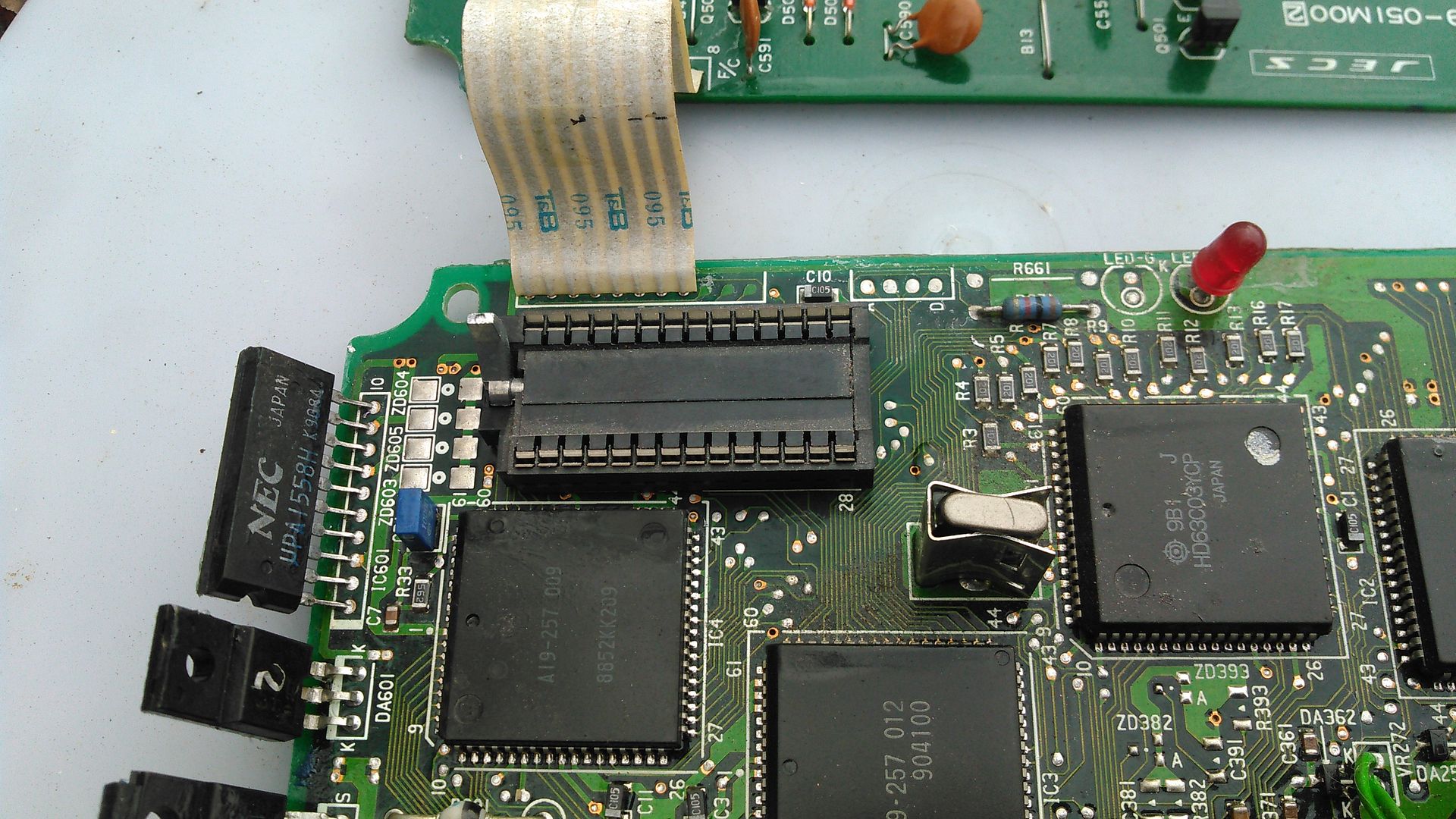
Hold the Chip into place while you solder the four corners of the chip, then solder it all..
Hit it with the Brake Cleaner once again, and the Chip Socket is done.. 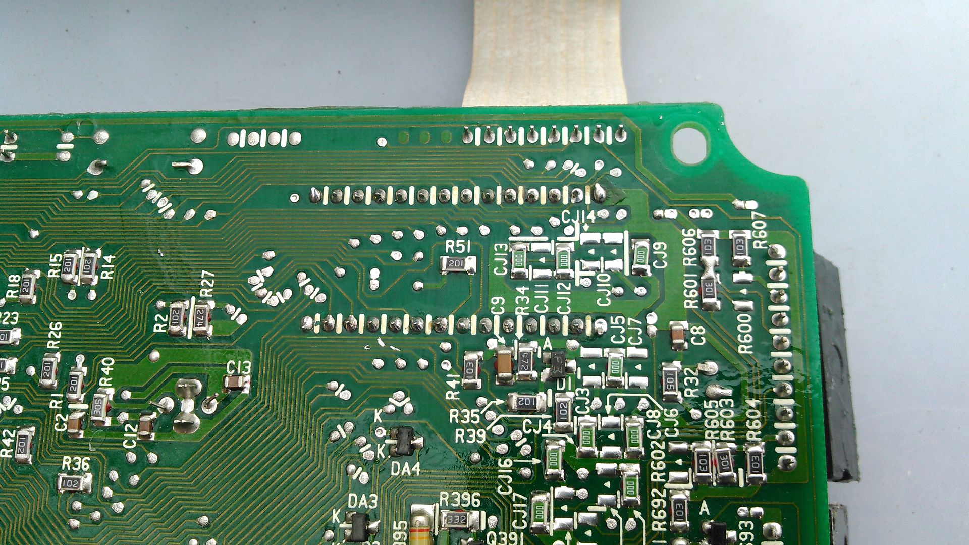
Now the reassembly.. When you removed the Transistors from the side of the ECU Frame, this left some gunk on the Transistors.. Clean it off with the Brake Cleaner Spray, and clean the Side of the ECU Case.. I install some Heat Sink Grease, to allow better thermal conductivity than the original install.. 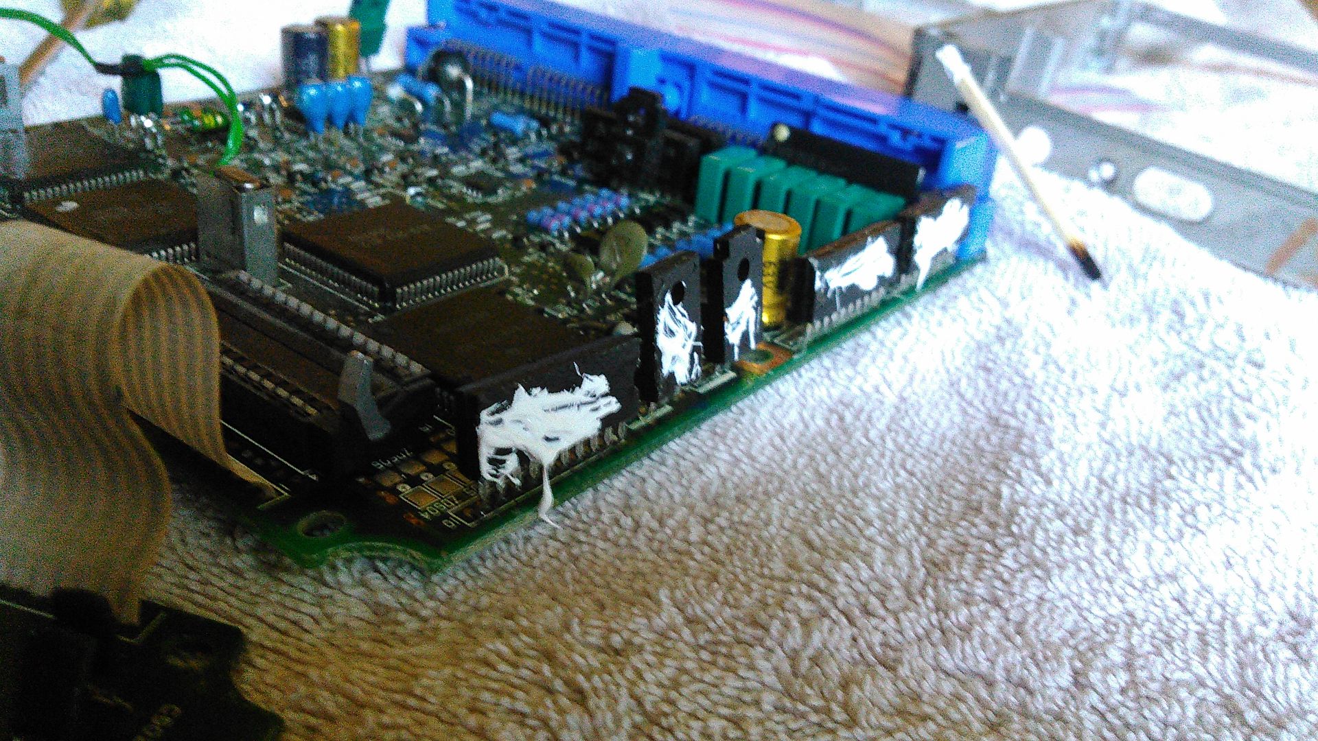
Now just reassemble as normal.. LIKELY you will need to apply a little Brake Cleaner Spray to the screws you removed, as the ‘Fingernail Polish’ that is on the threads still will be gummed up, and need a little help staying plyable..
|


 Chipping the ECU -