| Power Steering Pump Rebuild Following is a procedure to rebuild the Power Steering (PS) Pump on a 1990 - 1993 Twin Turbo Z. The procedure will also work on N/A's and Twin Turbo's from 1994 -1996 and will be easier and quicker because you will only have a single chamber pump instead of the dual chamber pump of the 1990 - 1993 twin turbos. Tools/Parts Needed:
- Pages ST- 54 through ST- 57 of the service manual. If you don't have a manual, it can be found here: [ http://300zx-twinturbo.com/cgi-bin/manual.cgi ] in the Steering System section.
- Bench vise
- Small torque wrench
- Torx (star) T-30 bit or T-30 screw driver
- Sockets: deep 14 mm, regular 19mm (if you don't have a deep 14 mm socket you can use a short extension)
- 2 ratchets (3/8" or 1/2," doesn't matter, but they need to be used simultaneously on your 14mm and 19mm sockets
- Snap ring pliers
- ~1" wide flat chisel
- Seal puller
- Small set of picks
- Small screwdriver (to pry out driveshaft seal)
- Pair of latex gloves
- Several rags and towels on hand
- Engine degreaser or other cleaner of your choice
- Small detail brushes
- Roll of paper towels
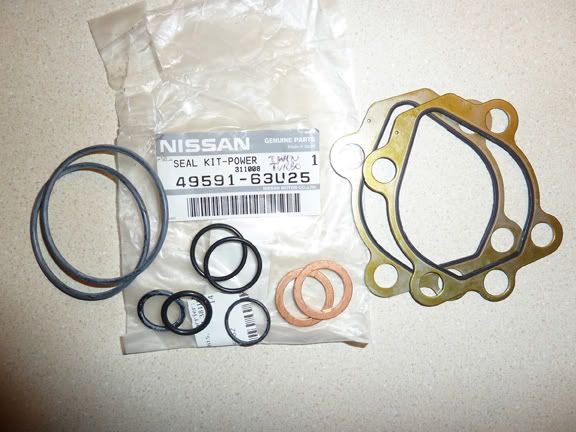
- PS pump rebuild seal kit (part # 49591-63u25 for TT 90 - 93), (part # 49591-63u26 for NA 90-96 and TT's 94 - 96, will not have as many o-rings and a gasket)
- PS shaft seal kit (part # 49119-03u25)
- 4 large copper crush washers (Part #49726-Y0100) for the high pressure and HICAS hose (you will need to replace these washers when you go to re-install the pump)
[pic 299]
Optional:
- Option #1: Pump driveshaft with new bearing, approximately $50 (in 2012)
- Option #2: New bearing to replace bearing on your existing driveshaft. The old bearing will need to be pressed off and the new bearing pressed on at a machine shop. I went this route and got a bearing from Grainger for $12 and a guy pressed the old one off and the new one on for free at a local machine shop in about 5 minutes. I used an NTN replacement bearing, part # 6202LLBC3/EM, 6202LLBC3/L627 labeled on the box.
Estimated Time to rebuild the pump:
~2 hours your first time.
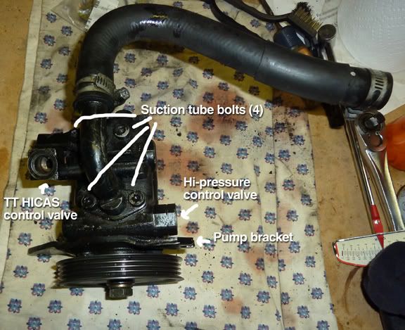
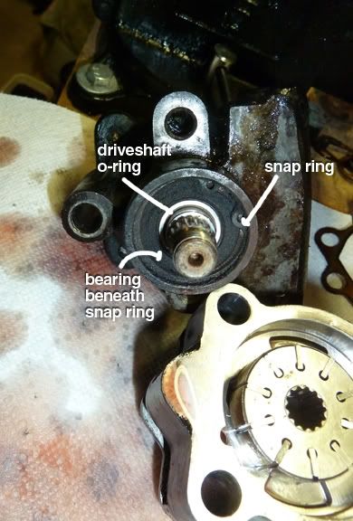
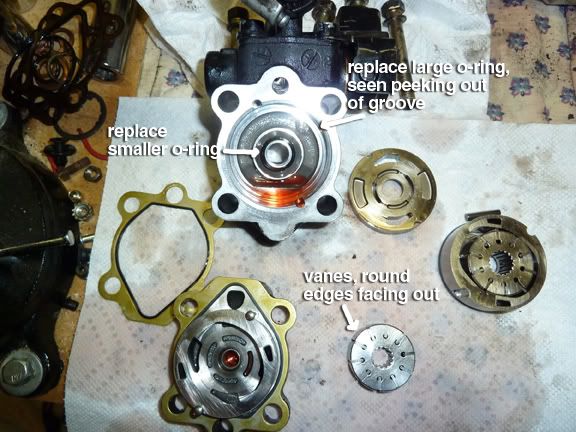
1. Before you disassemble the pump you need to thoroughly clean it, so that any debris caked on the outside of the pump does not fall into the pump openings when you have it apart. Put on your latex gloves and then use the degreaser, brushes, and rags to do this now. 2. Refer to service manual pages ST-54 through ST-57 for an exploded view of the parts and basic rebuild instructions. As with most things in the manual, detail is a bit lacking which is why I did this writeup to fill in the gaps. :-) [ http://300zx-twinturbo.com/cgi-bin/manual.cgi. ] Pic below also shows labels of some of the pump items.
[pic 334]
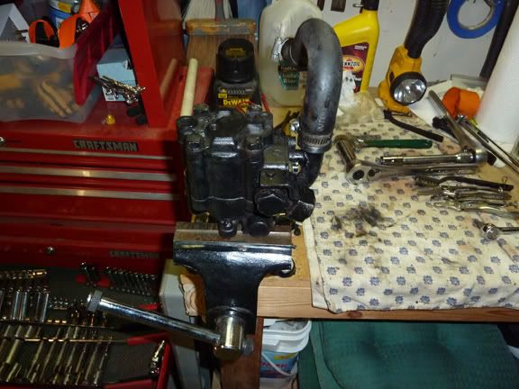
3. Place pump in your vice as shown with the suction pipe fitting facing up.
[pic 335]

4. Remove the pulley (19 mm). To keep it from turning while you loosen the nut, place your 14 mm socket on one of the bracket bolts behind one of the pulley openings and hold it stationary while you use your other ratchet to loosen the pulley nut. Hopefully you've read this write-up before you've removed your pump and pre-loosened the nut while the pump was still on the car and being held in place by the belt on the pulley to make this task easier. :-) Take note of the difference between the front and back side of the pulley. Set it aside along with the locking washer and nut.
6. Remove the four T-30 suction pipe bolts. (2 bolts if you have an NA pump)
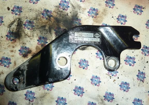
*Note: I had one bolt that was siezed so I had to dremel a slot in it and then use a large slotted screwdriver to remove later in the process. A royal pain. Hopefully your bolts won't have this problem. But when you see pics in the following steps below showing the suction tube still attached after this step, that is the reason. 7. Remove the pulley bracket bolts (14 mm x 2) and clean the bracket and the area around the pulley driveshaft. After I had cleaned the 1/8" layer of grime off it, lo and behold I could see a serial number on the bracket . :-)
[pic 336]
8. Remove control valves using 24 mm socket. Be careful not to drop the valves. They will want to spring out when the bolt is loosened. Fluid will seep out as well. Remove old copper washer and o-rings and replace with new ones from the kit. I used a small pick to remove the o-ring from the valve.
[pic 339 ]
[pic 340 ]
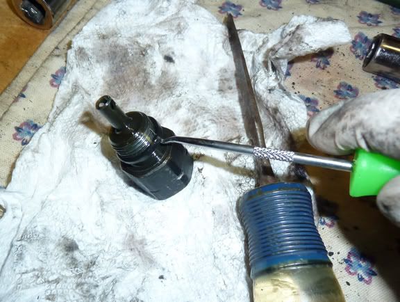
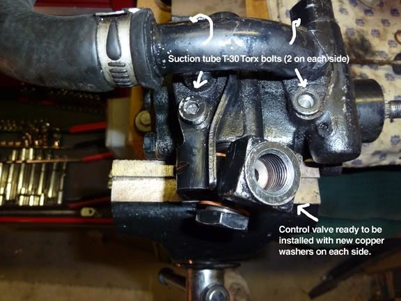
After replacing the washers and o-rings reassemble the control valves. Use torque wrench and tighten to 51- 58 lbs. It's important you tighten the fittings on the pump to the proper specs to prevent leaks later! 9. Reposition pump in vice so back of it (non pulley side) is facing up.
[pic 341]
10. Remove the rear housing (14 mm x 4). Replace the gasket with a new one, taking note of proper position compared to old one, and set aside on a clean rag.
[pic 342]
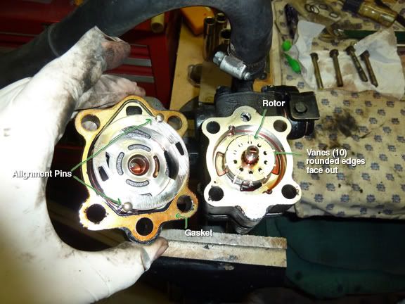
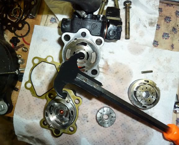
11. Carefully remove the cam ring rotor and other parts. Don't lose any of the vanes or pins (the pins may be still stuck in the rear housing you just removed). The vanes may fall out which is no big deal as they easily go back in. If they fall out, insert them back in with the rounded edges facing out. Remove the large 0-ring and replace. Replace the small thin o-ring at the base of the driveshaft.
[pic 344]
13. Use a seal puller to pull the center housing front side plate out. Replace small inner o-ring.
[pic 346]
14. To replace the large o-ring, place it in the bottom then gently and evenly press the front side plate down in the center of it. Put a pin in each groove to help you keep it squarely aligned as you press it down. If you don't, it's easy to get it slightly cockeyed and stuck. Then you will have to pull it out again.
15. Remove the snap ring on the driveshaft using your snap ring pliers.
[pic 345]
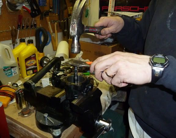
16. Reposition the pump in the vice so that you can place the flat side of your chisel perpendicularly on the end of the driveshaft to tap it out. The use of the flat side of the chisel over the end of the driveshaft is so you don't take the chance of deforming the end of the shaft with a misplaced strike of a hammer. Make sure you have something in place to catch the driveshaft so that it doesn't fall to the floor when you tap it out. I placed mine directly over the vice base so that it would hit it when I tapped it out. I also laid a thick towel on the floor below too for extra measure.
[pic 352]
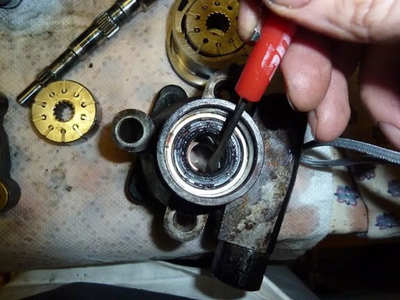
17. Turn the pump housing over and pry out the driveshaft seal using a small screw driver or pick. Coat the new seal with ATF fluid and replace. The edges of the seal should also have a small amount of grease applied to ease installation. I used some wheel bearing grease I had on hand. Press the new seal in by hand first, then place a 19 mm socket on it and tap it the rest of the way in with a hammer until the seal is flush. Wipe away any excess grease.
[pic 353]
Here's a pic of the various pieces.
[ pic 347]
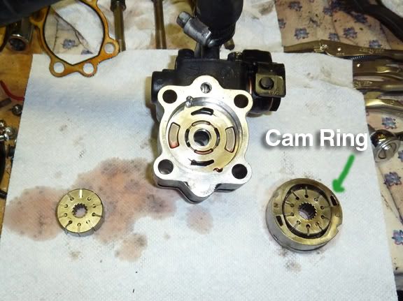
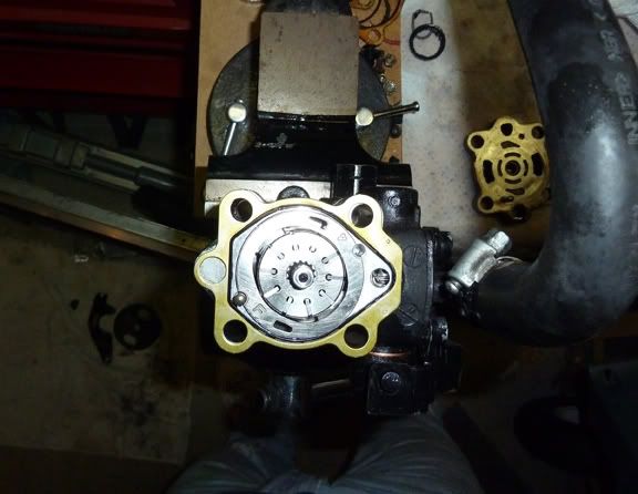
18. Tap in the driveshaft and replace snap ring. Turn housing over and reassemble. Be sure to put pins in first to help guide each cam ring down evenly. Again, make sure the rounded edges of the vanes face outward and all 10 vanes are still in place. Also make sure that new rubber gaskets are positioned properly where old gaskets used to be. Be sure bolt holes on gasket line up to ensure you have it right side up on the pump. Note that the "F" on the cam, seen in the bottom left of pic below, is facing up so you can see it.
[ pic 356]
19. Squeeze everything together as evenly as possible by hand, then put in the four long end bolts and hand tighten each of them. Then use a ratchet to tighten them in an X pattern so all bolts are tightened evenly. Use a torque wrench to do the final tightening to 23-31 lbs.
20. Replace suction hose bracket. Torque to 10-13 lbs. Be sure o-rings remain in the proper spots before tightening. It's easy for them to move out of place and then they can be crimped and damaged. (FYI, this was the area where I discovered my pump was leaking as the o-ring had dried up and no longer sealed.) 21. Replace front bracket with the serial number plate facing the pulley. Torque to 20 -26 lbs. 22. Replace pulley, flat side faces out. Put in 14mm socket and an extension on one of the bracket bolts to the hold the pulley from moving while you tighten the pulley bolt. Tighten to 40- 50 lbs. If you are unable to hold it and tighten it this much while on your bench, you can wait to do it once you've installed the pump back in the car, just don't forget to do it! Congratulations. You've now rebuilt your power steeing pump. Be sure to fill the reservoir with ATF Type III fluid after installation. Then follow this bleeding procedure: Jack front of car up so front wheels are off the ground. Start car. Turn steering wheel slowly from side to side until they lock. Repeat 4 or 5 times. Then check ATF reservoir. It will probably have dropped a bit. Top off to low point on reservoir float as necessary. Repeat turning wheels procedure until fluid level stays constant. Do not over fill. Hope this helps. Cheers.
doug8867
|


 How to Rebuild Your 300zx Power Steering Pump -