| The Ultimate Guide to Z32 Self-Diagnostics Whenever you get a Check Engine Light (CEL) or your car is acting funny, the first thing you should do is run codes. This guide will explain how to check, solve, and clear diagnostics codes on your Z32. US96 Z’s need not apply. Let’s get to it! RUNNING CODES
The first thing you need to do is check which, if any codes, are being thrown by your ECU. There are three ways to do this:
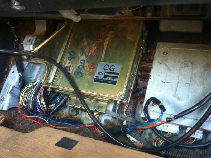
1. ECU Diagnostics Potentiometer (LED and CEL):
On the ECU itself is a red LED diagnostics mode light. Next to it is a small dial with a slot called a potentiometer. The dial has two positions: Mode I and Mode II. Mode I (all the way counter-clockwise) is normal operation. Mode II is diagnostics mode. Here’s how to enter diagnostics mode directly at the ECU: a. Pull back the carpet in front of the passenger seat from the top (closest to the dash). It’s held in place with Velcro.
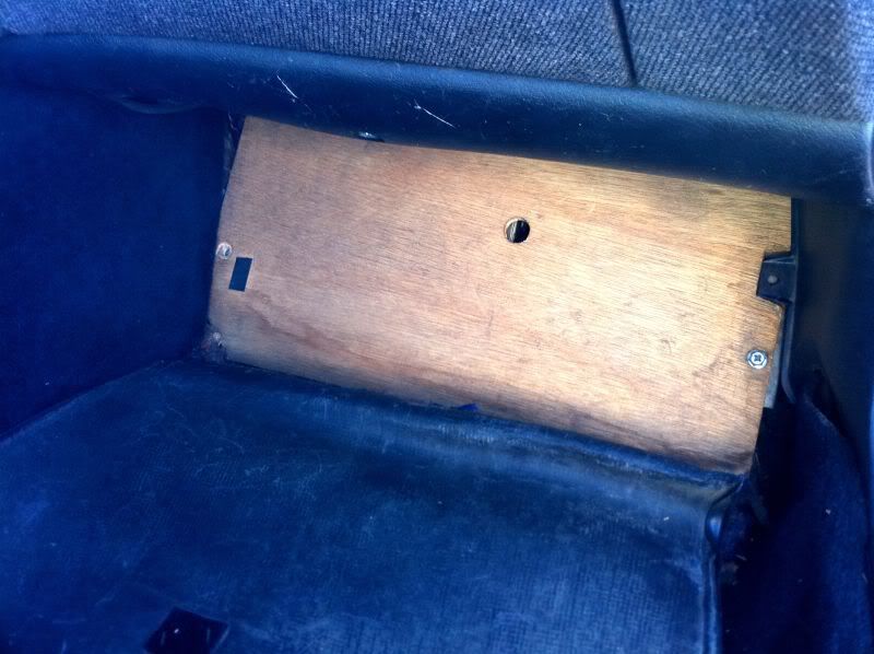 b. Remove the four 10mm bolts holding the wooden ECU cover down, and remove the wooden cover.
 c. Turn the key to the “ON” position (don’t start it).
d. Turn the potentiometer on the ECU all the way to the right (clockwise). Don’t over-turn it, it doesn’t take much effort to turn at all, and the light will turn off.
e. Wait 3 seconds with it in this position, then turn it all the way to the left (counterclockwise). The light will start blinking codes. The CEL will also blink the same way. LED won’t turn off? This could mean the potentiometer is already moved to Mode II or partway in-between, or the car is running. Check for these things and try again after cycling the key. 2. Consult Pins (LED and CEL):
You can also enter Mode II without even touching the floor board.
a. Locate the Nissan CONSULT Connector. It’s a gray connector on the driver’s side right next to the hood pull lever. If you can’t seem to find it, fish around behind the trim piece a little, as it may have popped off its post in the past.
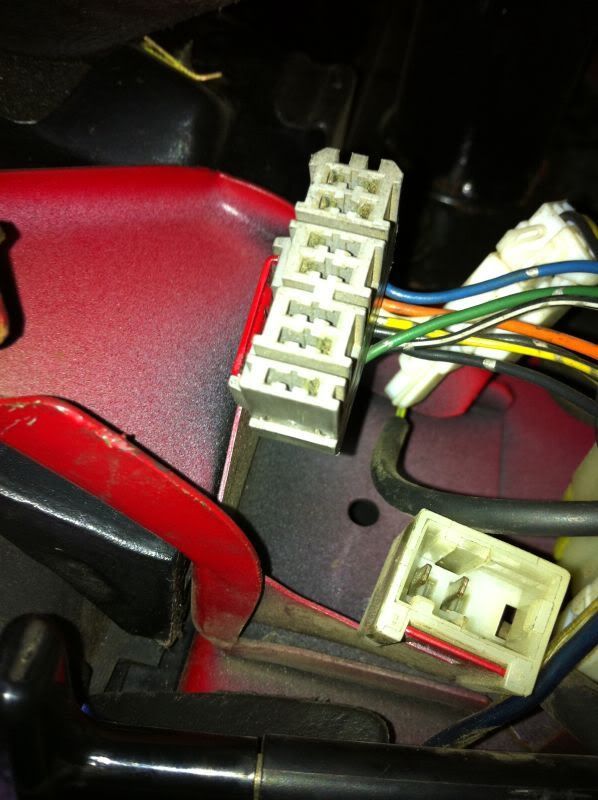 b. Using a paperclip, or small wire, jump the connection between pins 8 and 9 on the Consult connector, as shown below:
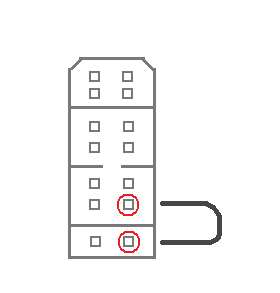 c. Hold the jump for three seconds, then remove the jump. This is essentially the same as turning the potentiometer on the ECU.
d. Once the jump is removed, the CEL will start blinking codes.
3. Consult Diagnostics (computers!): The easiest way of checking codes is using the Consult system. You can do this with a computer and a BlaZt Cable, for example. Software includes Conzult, Nissan Datascan, and several others. I’ll show this using Nissan Datascan (since that’s what I have).
a. Refer to the software instructions for details on installing the software, installing drivers, etc. This assumes you’ve already done all this.
b. Connect the Consult cable to the Consult Port on your car, and plug it into your computer.
c. Turn the key to “ON” (you can start the car if you want, but there’s really no point).
d. Launch the program.
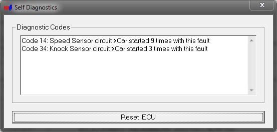
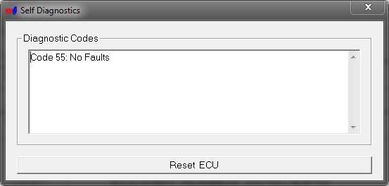
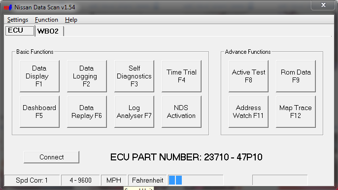 e. Click “Self-Diagnostics.”
f. The program will check the ECU for codes and display them and their meaning.
 If you used the third method, you’ve got your code, so you can skip down to the Code Index below to see what each one means and how to fix it. Otherwise, read on. READING CODES Now that you’ve gotten your car into diagnostics mode, you need to read the blinking lights to see what codes are displayed. The code is a two-digit number, represented by a series of long blinks for the first digit, immediately followed by a series of quick blinks for the second digit. Then a long pause, then the next code (or the same again if there’s only one). For example, Code 34 (Detonation Sensor Circuit) would read like this: 
If you’re reading off the CEL, it would blink the same way.
CODE INDEX
Here is a list of all the codes our cars can return, and their meanings (Thanks TTZD):
11: Crank Angle Sensor Circuit
12*: Mas Air Flow (MAF) Sensor Circuit
13*: Engine Coolant Temp Sensor Circuit
14: Vehicle Speed Sensor Circuit
21: Ignition Signal Circuit
26*: Boost Pressure Sensor Circuit
31*: ECU Malfunction
32*: EGR Valve Malfunction
33* Exhaust Gas (O2) Sensor Circuit (Left)
34: Detonation Sensor Circuit
35*: EGR Temp Sensor Circuit
42: Fuel Temp Sensor Circuit
43*: Throttle Position Sensor Circuit
45*: Fuel Injector Leak
51*: Fuel Injector Circuit
53*: Exhaust Gas (O2) Sensor Circuit (Right)
54: Signal Circuit from A/T to Transmission Controller Unit.
55: No malfunction.
* May cause the CEL to illuminate under normal (Mode I) operating conditions. Most codes, as you can see, are triggered by a component CIRCUIT. A common misconception is that a code tells you a component is broken or malfunctioning. 99% of the time, the component is fine the code is thrown because the CIRCUIT (read: the wiring) has a problem, like an open (broken) connection or (more rarely) a short circuit. On rare occasions, a malfunctioning component CAN return voltage/ohms so abnormally high or low that the ECU throws a code, but not usually. Incidentally, when a component does fail, it usually doesn’t throw a CEL. This is why a multimeter is your best friend—so you can ohm test every component in your engine bay! RESOLVING FAULTS:
Onto the juicy stuff: Fixing that crap! Here’s a few things I might refer to several times in these descriptions:
-“Clean”: This doesn’t mean wipe it off with a rag. Get some electrical component cleaner from the auto parts store, spray it down and soak it. Then use a wire brush (gun cleaning kits work great!) to scrub away any dirt, green corrosion, etc. Fill the connector with dielectric grease if you want (this will help prevent corrosion in the future).
-Spring Clips: Many connectors in our engine bay use these stupid little spring clips, which are just tensioned metal clips squeezing around the connector to prevent it from falling off. Remove them with dental/mechanic’s picks, or a small screwdriver and some needlenose pliers. Once you get the connector off, replace the spring clip—the connector will push back together without it, and this will prevent you from losing the spring.
-Resetting/clearing codes: Clearing the codes from the ECU (there’s a details about this at the end). CODE 11: CRANK ANGLE SENSOR CIRCUIT.
a. Disconnect the battery. Place the terminals so that it cannot come into contact with the battery posts.
b. First, we need to check the connector to the CAS. Start by removing the tube to the driver’s side throttle body.
c. Remove the spring clip and pull the connector. Replace the clip.
d. Clean the terminals on the CAS connector.
e. Check to see if any of the pins have popped out the back of the connector, there should be four total.
f. Clean the pins on the CAS itself. If you have to remove the CAS, be sure to mark its position before you do, and reinstall in the same spot.
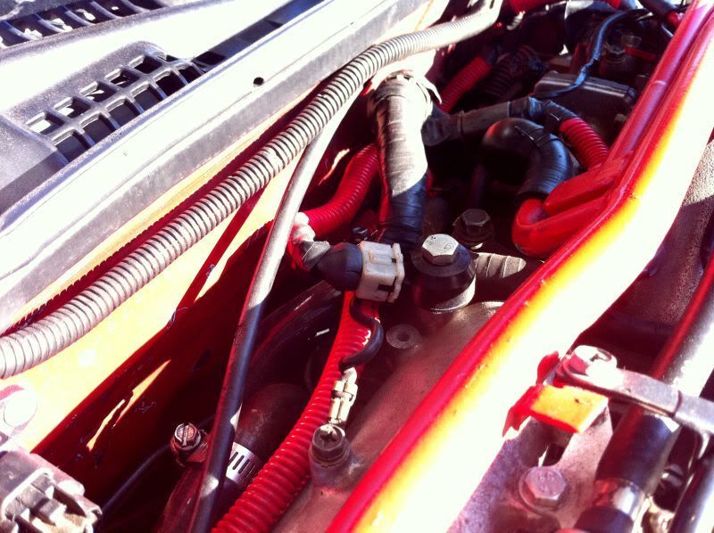
g. Check Ground F11, which is located towards the rear of the engine bay, near the fuel pressure regulator (driver’s side), just behind the balance tube.
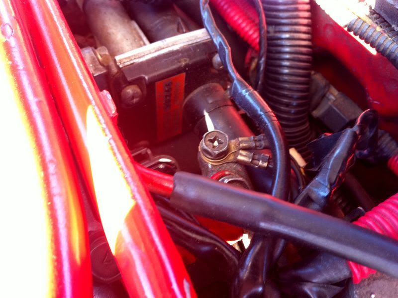 h. Check connector F23, which is the white connector by the Relay Box on the driver’s side of the engine bay. Clean if necessary (these connectors seal a lot better than those on the CAS itself, so this usually isn’t a big issue here).
Note that in most cars, the bundle of connectors will be to the RIGHT of the Relay Box. I moved mine over to make room for my PTU. i. Clear codes and run them again. If the code persists, replace the Crank Angle Sensor. CODE 12: MAS AIR FLOW SENSOR CIRCUIT.
a. Disconnect the battery. Place the terminals so that it cannot come into contact with the battery posts.
b. Remove the two 10mm bolts (four if you have SRS) holding the nose panel down. Remove the nose panel.
 c. Remove the spring clip and pull the connector to the MAF sensor. Replace the clip.
d. Clean the terminals on the MAF sensor connector.
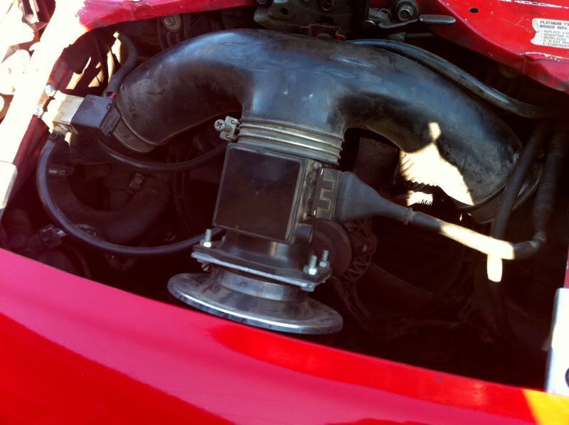
e. Clean the pins on the MAF itself. While you’re in here, verify that it’s an N62 MAF (it should say so on the stamp on the left side).
f. Check ground F11, which is located towards the rear of the engine bay, near the fuel pressure regulator (driver’s side), just behind the balance tube.
g. Check connector F23, which is the white connector by the Relay Box on the driver’s side of the engine bay. Clean if necessary (these connectors seal a lot better than those on the CAS itself, so this usually isn’t a big issue here).
h. Clear codes and run them again. If the code persists, replace the MAF sensor. CODE 13: ENGINE COOLANT TEMP SENSOR CIRCUIT
a. Disconnect the battery. Place the terminals so that it cannot come into contact with the battery posts.
b. Ensure that the car has fully cooled off and coolant system pressure is released (Remove the radiator cap but BE CAREFUL if you think it even MIGHT be hot!)
a. Locate the Coolant Temp Sensor. On the upper radiator pipe, behind the coolant fan, are two sensors. The right one is the sensor for the gauge, the left one is for the ECU. We’re interested in the left one.
b. Remove the spring clip and remove the connector. Replace the spring clip.
c. Clean the terminals on the connector.
d. Remove the temp sensor (A socket fits over it, but I can’t remember what size!)
e. Check the probe end for heavy buildups of corrosion, rust, any breaks, cracks, etc. Clean or replace if necessary.
f. Clean the pins on the temp sensor itself.
g. Replace the temp sensor, reconnect the connector.
h. Reset codes, run them again. When you turn the key to “ON,” the auxiliary fan will turn on if the temp sensor circuit is open. If the code persists, replace the temp sensor. CODE 14: VEHICLE SPEED SENSOR
a. Disconnect the battery. Place the terminals so that it cannot come into contact with the battery posts.
b. Jack up the car. Use all the necessary safety precautions.
c. Locate the vehicle speed sensor. On the passenger side of the transmission, there are three devices. The speed sensor is the one closest to the engine. It's also the only device under here with two screws holding it in.
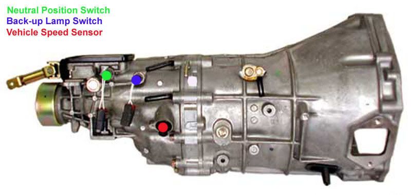 d. Unplug the connector to it (simply squeeze the locking tab and pull them apart). Check both sides for dirt and corrosion, and clean as necessary.
e. Follow the wires up to make sure there are no breaks.
f. Reset the ECU and run codes again. Take it around the block and see if the speedometer is working. If not, pull the gauge cluster (read on).
g. Remove the gauge hood (two Philips screws accessible from underneath the hood). Pull towards you, and then left up. Be careful not to break the tabs.
h. Remove the bolts holding the gauge cluster to the metal bracket.
i. Remove the Climate Control and Headlight control pods (two Philips screws underneath each).
j. Carefully unplug all harness connectors (they all have locking tabs you have to squeeze).
k. Remove the Hazard Light switch. Pull the switch itself directly UP until it pops off. Remove the two Philips screws holding the switch, and unplug the connector.
l. Remove all bolts & screws(two on the bottom, two on the top for each pod) holding the pods in. Remove the pods.
m. Disconnect the harnesses at the top corners of the gauge pods. Slide them off the mounts and out of the way.
n. Remove the bezel surrounding the gauge (pry it towards you).
o. Remove the two screws on the lower side of the gauge cluster.
p. Disconnect the harness connectors and remove the gauge cluster.
q. Turn the cluster around so you’re looking at the backside. At the bottom are two screws. Remove them.
r. Remove the tabs holding the plastic cover in place, remove the plastic cover.
s. Undo the tabs holding the two halves of the gauge cluster together. Remove the black cover in the front.
t. There are a set of screws directly behind the speedometer (8 for the 90TT, don’t forget those holding in the boost gauge). Remove these.
u. Carefully remove the speedometer.
v. There are multiple solder joints where the speedometer’s circuit board is mounted (the screw holes). Check them for cracks/breaking. Melt and reset the solder for ALL broken/cracked/questionable solder joints you can safely access. These cracks/breaks can cause a bad connection, which throws the code.
w. Using a soft art eraser, clean the terminals on the gauge cluster connector holes. Be careful with these ribbon cable things.
x. Using the same art eraser, clean the connector pins on the harnesses to the gauge cluster.
y. Put all that crap back together! It’s the reversal of the removal; no surprises.
z. Clear codes and run them again. If the code persists, replace the speedometer. If the code disappears but the speedometer still acts crazy, proceed.
aa. Jack up the car and disconnect the speed sensor connector. With the car in Neutral, turn the back wheels while reading the resistance across the terminals of the speed sensor with your multimeter. You should see the continuity change as you turn the wheels. If it goes crazy, you may have to replace the speed sensor.
bb. If it doesn’t move, pull the speed sensor (two bolts, one on each side). Check the pinion gear for slipping or broken teeth. If it’s fine, replace the speed sensor.
cc. Reassemble, clear codes, and try again. Oy. CODE 21: IGNITION SIGNAL CIRCUIT:
a. Disconnect the battery. Place the terminals so that it cannot come into contact with the battery posts.
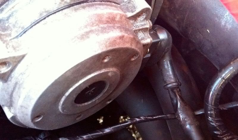
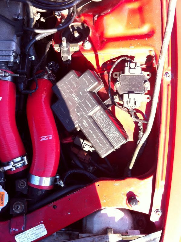
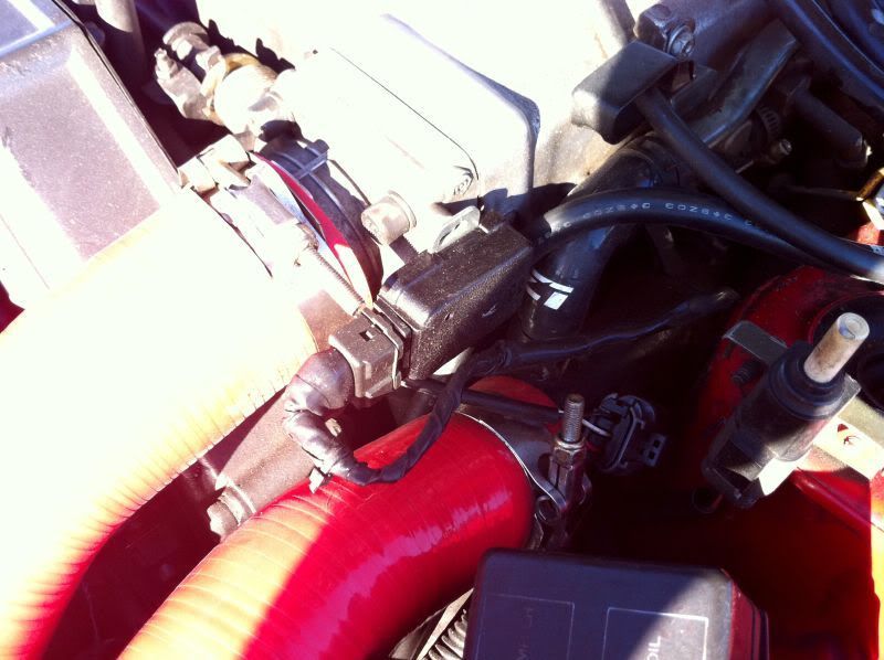
b. Locate the PTU. From the factory, it’s mounted on the passenger side of the timing belt cover, behind the upper water pipe and the left throttle body hose. Remove these for better access.
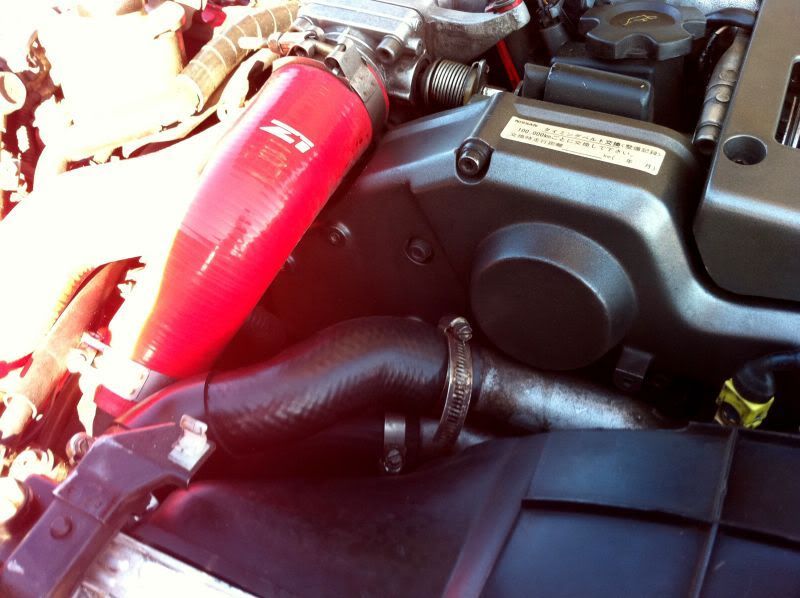
The factory location of the PTU
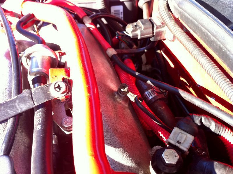
Where mine lives; I also deleted the subharness.
c. There are two styles of PTU. The old-style is a large rectangular box, with a metal heatsink on the cover. If you have this kind, REPLACE IT. If you’re in the US, you can get the dealership to replace it for free. If not, buy the PTU Service Campaign kit. This unit was recalled in ~92 for failing (ie dies when it gets hot). It was replaced with the new style, which had new connectors, so older cars had a subharness installed to adapt the connectors over.
d. If you have the new style (small black box) proceed: Remove the two bolts holding the PTU to its bracket.
e. Disconnect the metal clips holding the connectors to the subharness connectors. Replace the clips.
f. Disconnect the connectors at the PTU itself by squeezing the tabs and pulling.
g. Check the PTU pins for corrosion and clean as necessary.
h. Check the pins of the subharness for corrosion and clean as necessary. Verify that none of the pins have been pushed through the back.
i. Check the terminals of the subharness (where it meets the PTU) for corrosion. Also check the car’s harness connectors for corrosion.
j. Reassemble.
k. Check connectors F23 and F25 (the white and brown connectors by the Relay Box). Clean as necessary.
l. Check the connectors to each coilpack. These frequently break and don’t seat properly, but can be easily replaced if this happens. Make sure all seat ok, and that there aren’t any broken/shorted wires (shorted wires will melt a coilpack within ~30 seconds, so you’ll know).
m. Check your fusible links (the small cover by the battery). Replace as necessary.
n. Check ground F39. This is located towards the back of the engine behind the balance tube. NOTE if this ground is loose/disconnected, attempts at starting may burn up the PTU.
 o. Clear codes and run them again. If it persists, replace the Ignition Circuit Relay under the relay cover box with a known good relay.
p. Clear codes and run them again. If it persists, replace the PTU. CODE 26: BOOST PRESSURE SENSOR CIRCUIT
a. Disconnect the battery. Place the terminals so that it cannot come into contact with the battery posts.
b. Locate the boost pressure sensor. It’s the small black box located on the driver’s side of the engine bay, near the brake booster. It has a vacuum line going to it.
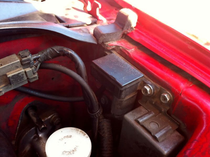 c. Disconnect the connector (squeeze the tab and pull DOWNWARDS). Check for corrosion and dirt, and clean as necessary.
d. Remove the Boost Pressure Sensor. Clean the pins on its connector.
e. Replace and reassemble. Clear codes and run them again. If it persists, replace the boost pressure sensor.
f. Don’t forget to verify that the vacuum line going to the boost sensor is in good shape while you’re in here! This will ensure your factory boost gauge is as accurate as possible (which isn’t very, as it turns out). CODE 31: ECU MALFUNCTION
a. Ensure that the diagnostics potentiometer on the ECU is rotated fully counterclockwise. Do not force it, the slot will line up with the “MODE I” label.
b. Turn the key to “ON.” The Check Engine Light and Diagnostics LED (on the ECU itself) should illuminate. If not, check the bulb, and try wiggling the LED on the ECU. If still no go, check the harness connector to the ECU.
c. Start the car. The light should go out. If it stays on, the ECU is bad. You might have an aftermarket EPROM that was installed backwards. Remove the ECU (three bolts on the bracket). Remove the bracket from the ECU (four bolts I believe).
d. CAREFULLY remove the four screws holding the cover panel on the ECU. They have blue loctite holding them in, and like to strip easily.
e. Remove the four screws holding the daughterboard down (the smaller board). Carefully lift it up and out of the way.
f. Locate the EPROM. It’s the 28 pin chip near the top of ECU harness connector. It has a small notch on one side. Ensure that the notch is facing the center of the ECU (and not towards the outside of the ECU). If it’s backwards, CAREFULLY pull it straight up and replace it.
g. If the EPROM is fine (or stock), replace the ECU. CODE 32: EGR MALFUNCTION
a. This code is thrown when the EGR valve won’t actuate, it’s very simple to test. Locate the EGR at the back of the engine bay. It’s pretty far down there (between the engine and the firewall) but has a large circular assembly on the top.
b. The EGR valve has a vacuum tube coming out the side (or should…). Follow the vacuum line to its source, and ensure that it’s hooked up properly. Refer to my vacuum diagrams TT or NA.
c. While you’re fiddling with the EGR vacuum lines, try sucking on the vacuum line running to the EGR valve. When you let off, you should be able to hear the valve “plop” closed. If not, replace the EGR (or bypass it!)
d. Reassemble, clear codes, and run them again. CODE 33: EXHAUST GAS SENSOR CIRCUIT (LEFT):
a. Disconnect the battery. Place the terminals so that it cannot come into contact with the battery posts.
b. Locate the O2 sensor on the driver’s side. It can be difficult to see with the brake booster in place, but it’s there.
c. Follow the wires coming off the O2 sensor up to the connector. Remove the connector and clean the pins on both sides.
d. Reassemble. Clear and run codes. If the problem persists, replace the O2 sensor (can easily be done by removing the brake booster) CODE 34: DETONATION/KNOCK SENSOR CIRCUIT:
a. Locate the Det Sensor harness connector towards the back of the engine. There are two very similar connectors which often get mixed up.
b. The Det sensor is located UNDER the lower intake manifold. Find the lead that’s running under the intake manifold. It SHOULD be hooked up to the connector with gray and white wires.
c. There’s another connector with green/black and red/black wires. This SHOULD be connected to the driver’s side VTC connector (which has white sheathing around it).
d. Don’t forget to clean all connectors while you’re in here!
e. Clear and run codes. If the code persists, read on.
f. Go to Radioshack and buy a 1 Megaohm (1000k) resistor. Shove it in the det sensor connector going to the ECU (again, the one with the gray and white wires). Reset codes and run them again. If the code is gone, you need to replace your detonation sensor. Many people have relocated it to the back of a head, or to the upper intake manifold. It won’t be as effective, but it works.
Mine has been relocated to the back of the plenum. g. If the code persists, check the ECU harness connector. CODE 35: EGR TEMP SENSOR CIRCUIT.
First, have you recently replaced your ECU? If so, you might have a Federal car with a California ECU, as the EGR temp sensor was only present on Cali cars. If not, read on:
a. Disconnect the battery. Place the terminals so that it cannot come into contact with the battery posts.
b. Locate the EGR temp sensor towards the back of the car. It’s a rectangular, black and red connector (it’s identical to the wastegate solenoid connectors if you’ve ever seen them). Disconnect and clean it.
c. Clear and run codes. If it persists, replace the EGR temp sensor. Alternatively, you can use a 68K Ohm resistor (Radioshack). “Plug” it into the harness connector (ECU side). Clear and run codes. If it persists, check the ECU harness connector. CODE 42: FUEL TEMP SENSOR CIRCUIT:
a. Disconnect the battery. Place the terminals so that it cannot come into contact with the battery posts.
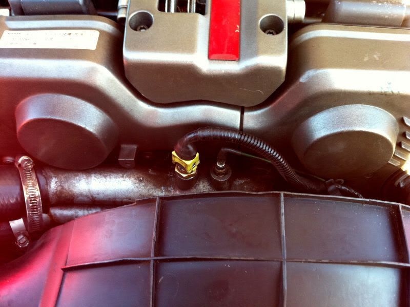
b. Locate the Fuel Temp Sensor. It’s between the intake runners for cylinders 2 and 4, on the driver’s side of the engine bar. It’s a single-wire connector that leads directly to the ECU harness.
c. Check the connector (all of it…) for dirt or corrosion. Check for breaks in the wire, and check to see that the terminal on the fuel temp sensor itself is not loose. If it is, use a punch on its rivet to snug it down again.
d. Check the ECU harness. Clear and rerun codes. If it persists, replace the Fuel Temp Sensor (it’s cheap and easy! You don’t even have to depressurize the fuel system, just unscrew it and screw in the new one). CODE 43: THROTTLE POSITION SENSOR CIRCUIT:
Note that this is for the throttle position sensor (the pigtail coming off the TPS; it reads the variable throttle position)—NOT the hard idle switch, which will not throw a code.
a. Disconnect the battery. Place the terminals so that it cannot come into contact with the battery posts.
b. Locate the TPS, it’s on the driver’s side throttle body. The connector directly on the front is for the hard idle switch, which is not related to this.
 c. Check the harness connector (the wire coming off the TPS). Clean as necessary, and run codes again. This connector likes to come unplugged after the connectors break over the years.
d. Clear and run codes. If it persists, try refurbishing the TPS. If it STILL persists, replace the TPS unit. CODE 45: FUEL INJECTOR LEAK
I’ve NEVER see this code actually thrown, as the ECU usually isn’t able to determine this kind of thing. In any case, here’s how you can solve it.
a. Disconnect the battery. Place the terminals so that it cannot come into contact with the battery posts.
b. Remove the gas filler cap. Place it loosely in place, but don’t tighten it enough to create a seal.
c. Remove the Fuel Pump Fusible Link in front of the battery.
d. Crank the car. If it starts, let it run until it dies. When it dies, crank it over a couple of more times until it won’t “catch” anymore.
e. Remove the intake manifold.
f. Mark the position of the Crank Angle Sensor. Leave it connected, but remove it from the head (three 10mm bolts).
g. Turn the key to “ON” (don’t attempt to start it). Slowly rotate the CAS. You should hear each of the six fuel injectors click. If you hear one that’s not clicking, take note of which injector it is, as it’s stuck open and will need to be refurbished or replaced.
h. If they all click, remove all the fuel injectors, an replace all of their O-rings with new NISSAN OEM parts. Lubricate the O-Rings with motor oil when you install them, and be careful not to pinch any. Don’t draw them in with the caps. You’ll also need to do this for the fuel injector you replace, if it’s just one.
i. Reassemble, reset codes, and try again. You may have to run for a while to ensure that this code is gone. CODE 51: FUEL INJECTOR CIRCUIT:
This code indicates that a fuel injector is shorted OPEN, which is pretty tricky for this to happen! If a fuel injector connector is shorted closed, it won’t throw a code, but will instead FRY YOUR ECU.
a. Disconnect the battery. Place the terminals so that it cannot come into contact with the battery posts.
b. Pull the connectors to ALL fuel injectors. If you have early style connectors, this involves removing the spring clips which can be very tricky. You can replace them, but personally I wouldn’t blame you for putting a dot of RTV on the connector and calling it good ;).
c. Using a multimeter, check for continuity between the pins on the injector harness connectors and body ground. With one of the pins (not both!) continuity should exist. You have one without continuity on either pin, check your ECU connector. Otherwise you may have a broken wire in the harness somewhere.
d. Using a multimeter (and some long wires!) check for continuity between pins at the ECU harness and the Injector connectors as shown below.
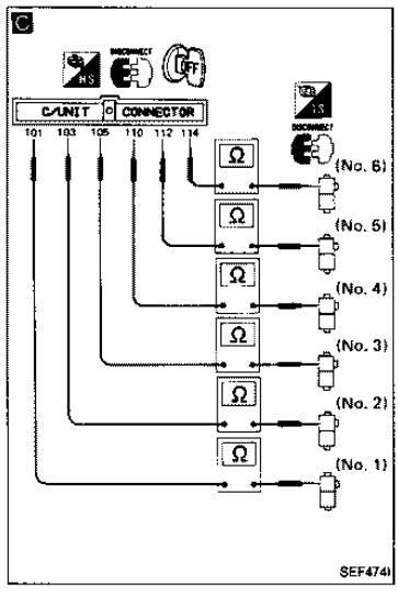 e. Clear and run codes again. If it persists, consider replacing your wiring harness and ECU. CODE 53: EXHAUST GAS SENSOR CIRCUIT (RIGHT):
a. Disconnect the battery. Place the terminals so that it cannot come into contact with the battery posts. REMOVE THE BATTERY.
b. Locate the O2 sensor on the passenger’s side.
c. Follow the wires coming off the O2 sensor up to the connector. Remove the connector and clean the pins on both sides.
d. Reassemble. Clear and run codes. If the problem persists, replace the O2 sensor (can easily be done by removing the brake booster) CODE 54: SIGNAL CIRCUIT FROM A/T TO TRANSMISSION CONTROL UNIT:
a. Disconnect the battery. Place the terminals so that it cannot come into contact with the battery posts.
b. Check and clean connector F25, which is the brown connector by the relay box on the driver’s side of the engine.
c. Check and clean connector E35, which is the blue connector in front of the passenger side shock tower.
d. Check body ground E13, which is located between the Relay Box and the Driver’s Side Headlight.
e. Check and clean the Neutral Switch (A12) connector, which is the black connector running from the transmission to the engine bay.
f. Clear and run codes. CODE 55: ALL SIGNALS NORMAL.
a. Go drive your Z!
CLEARING CODES:
Clearing codes is very simple, but MUST be done after you make any changes to see if you actually fixed anything. If you don’t clear the codes, they’ll hang around forever and show up every time you run codes. A common misconception is that disconnecting and reconnecting the battery will clear codes, but it won’t—this simply clears the ECU’s self-learn function, which is just a Base A/F tweak… you probably won’t even notice. To clear codes, you basically enter and exit MODE II twice. There are three ways to do this:
1. At the ECU:
a. Pull back the carpet in front of the passenger seat from the top (closest to the dash). It’s held in place with Velcro.
b. Remove the four 10mm bolts holding the wooden ECU cover down, and remove the wooden cover.
c. Turn the key to the “ON” position (don’t start it).
d. Turn the potentiometer on the ECU all the way to the right (clockwise). Don’t over-turn it, it doesn’t take much effort to turn at all, and the light will turn off.
e. Wait 3 seconds with it in this position, then turn it all the way to the left (counterclockwise). The light will start blinking codes. The CEL will also blink the same way.LED won’t turn off? This could mean the potentiometer is already moved to Mode II or partway in-between, or the car is running. Check for these things and try again after cycling the key.
f. Turn the potentiometer clockwise again, wait three seconds, and turn it back again. This will clear all codes.
g. Turn the key off, and run codes again to ensure they’re gone. 2. Consult Pins (LED and CEL):
a. Locate the Nissan CONSULT Connector. It’s a gray connector on the driver’s side right next to the hood pull lever. If you can’t seem to find it, fish around behind the trim piece a little, as it may have popped off its post in the past.
b. Using a paperclip, or small wire, jump the connection between pins 8 and 9 on the Consult connector, as shown below:
c. Hold the jump for three seconds, then remove the jump. This is essentially the same as turning the potentiometer on the ECU.
d. Once the jump is removed, the CEL will start blinking codes.
e. Insert the jump again, and hold for three seconds. Then remove it. This will clear all codes.
f. Turn the key off, and run codes again to ensure they’re gone. 3. Consult Diagnostics (computers!):
a. Refer to the software instructions for details on installing the software, installing drivers, etc. This assumes you’ve already done all this.
b. Connect the Consult cable to the Consult Port on your car, and plug it into your computer.
c. Turn the key to “ON” (you can start the car if you want, but there’s really no point).
d. Launch the program.
e. Click “Self-Diagnostics.”
f. The program will check the ECU for codes and display them and their meaning.
g. Click “Reset ECU.” The program will send the clear signal to the ECU, and then check for codes again, and display them (if any).
 Hope this helps you troubleshoot your Z. Good luck!
 |


 The Ultimate Guide to ECU Diagnostics -