| Steps to assembling a short block. Necessities: Clean work area
Gloves
Engine bag
Bungee cords
Tool Assortment (10mm, 11mm, 12mm, 13mm, 17mm sockets, piston ring expander and compressor, c-clip pliers, dead blow hammer)
PS: No harbor freight tools allowed
Plastigauge: Green
ATF
Lacquer/Mineral Oil (for cleaning)
Gasket Kit (oil pickup o-ring, oil tree o-ring, oil squirter gaskets must be purchased separately)
30mm 'deep' Brass Expansion Plugs (Napa)
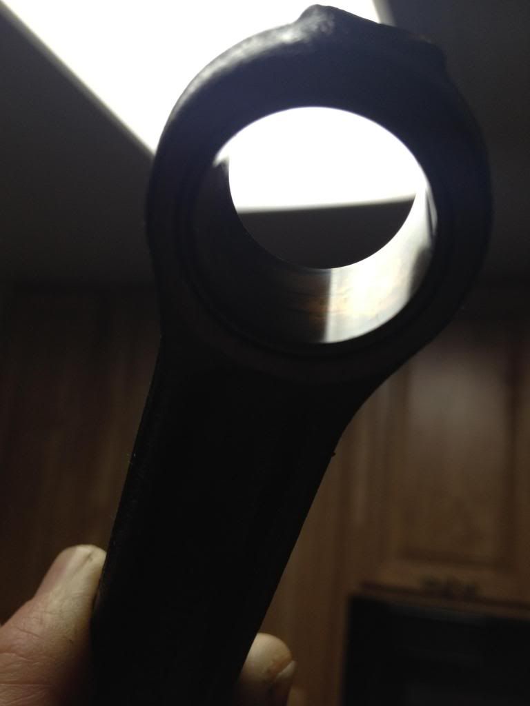
Compressed air (or air duster) Assumptions: Just having picked up your block from the machine shop, hot tanked, cleaned, prepped. You know how to use a wrench/calipers/feeler gauges. Working on a TT block with casting plugs, check valve plugs still in place. Special Precautions: Keep everything super super clean, tools, clothes, parts, etc. Any contamination can ruin your life. Preparation: A) If not already completed (most wont be), paint your block the desired color. Be sure to mask off the head surface, oil pan surface, front/rear mounting surfaces for oil pump, rear seal, water pump, etc. B) If you are replacing pistons/rods: Inspect the pin clearances/interference on the piston and rod. I used a Mueller gauge set to 0.866" (pin diameters) to measure the interference on the piston (which was ~0.001" on all) and clearance on the wrist pin bushing (about 0.0006" on mine) If they check out, continue, if not correct the issue (likely requiring machining) and return later! Install one wrist pin clip in each piston (rounded side out, refer to FSM) Inspection of rod/pin bushings:
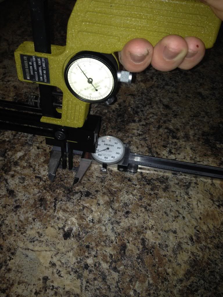
 Setting Mueller gauge:
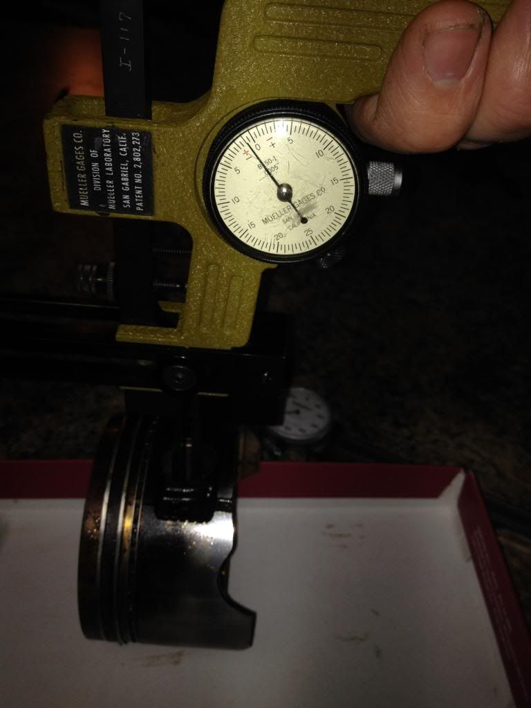
 Measuring interference:
 Alternatively, you can measure the piston holes, connecting rod hole, and wrist pin to calculate the clearance/interference. Piston Hole: 0.8656"-0.8661"
Connecting Rod Bushing: 0.8664"-0.8670"***
Wrist Pin: 0.8657"-0.8662" *** More Important is the clearance between the wrist pin and the connecting rod bushing: 0.0002"-0.0007" C) Place your CLEAN wrist pins in the freezer on some sort of clean plastic tray. Set your oven to the lowest temp (200F on mine) and put the pistons in the oven, as many at a time as you are comfortable with. I chose to do 2 at a time at 5 minute intervals. When the 5 minutes is up, pull the pistons out (oven mitts!) and insert the frozen pin into the piston, through the rod, and through the other side of the piston, bottoming out on the wrist pin clip. Ensure the rods are installed correctly, oil squirters in the right orientation. From looking at the top of the piston, with the front of the engine (dot on piston) to the right, the oil squirters should be pointing towards you. Don't forget to install the remaining wrist pin clip when the piston cools down. Make sure everything rotates smoothly. Set aside for later. Step D) Insert piston rings into the block. Use an old piston to push the rings in level (about 1-2" deep). Use a feeler gauge to measure the piston ring end gap. If necessary, file to within factory spec. End Gaps:
Top Ring: 0.0083"-0.0157"
Second Ring: 0.0197"-0.0299"
Oil Rings: 0.0079"-0.0299" When you are done filing that ring, install it on the piston for that cylinder. Start with the lower oil ring and work your way up. If the rings are etched (letters and/or numbers) put the etching mark upwards. Measure piston ring side clearance onto the piston using a feeler gauge: Side Clearance:
Top Ring: 0.0016"-0.0029"
Second Ring: 0.0012"-0.0025" Make sure to deburr and clean your rings after filing 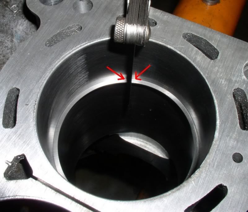
1) Clean your block thoroughly. Use mineral oil/lacquer to clean the cylinder walls, main journals until a paper towel comes out clean. Immediately cover the cylinder walls with a very light coat of ATF. If this is your stopping point for the night, lightly coat bare metal surfaces with WD40. 2) Install oil squirters and oil diverter plates into the block (above the crank). Tighten all bolts to 4.6-6.1 ft lbs (0.64-0.85 kg-m) using a 10mm socket. 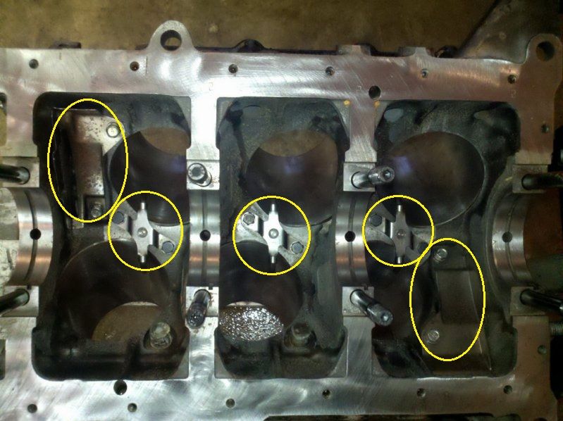
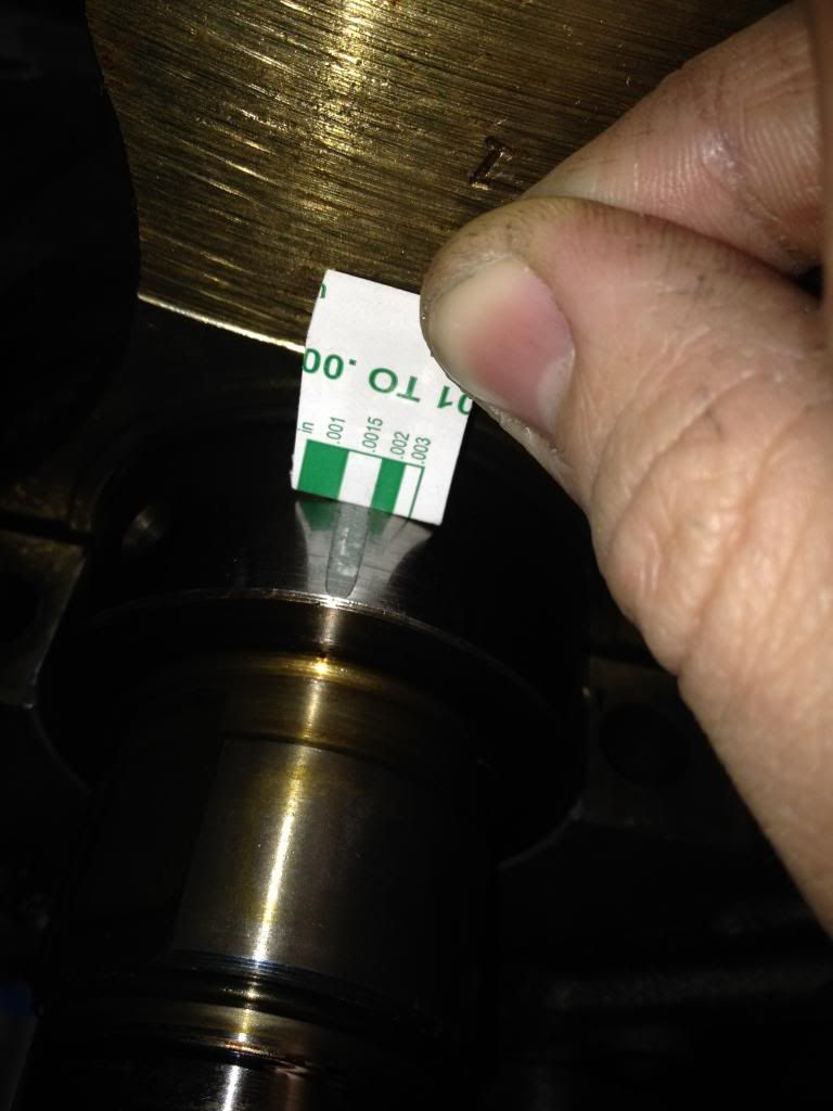
3) Clean expansion plug holes in block to be free of paint/oil. Install 12x BRASS (steel will rust over time) expansion plugs into the block. I used a 18mm socket to drive them in with a 3 lb hammer, lightly coat the perimeter with Permatex High Tack to prevent leaking. Drive them in until the top is just level/under the chamfer. Don't go too far or you can block the water passage slightly. 4) Clean main bearing races with lacquer. set the lower bearings in the block (they require minimal force) ensuring the tab is sitting in the guide, and the tops are roughly even with the deck surface. Rock the bearing back and forth slightly to fully seat it. Repeat for all 4 bearings. Repeat for the main caps (girdle). 5) Using your finger, put a THIN film of oil on the bearing surfaces, wipe with a cloth to ensure there is no puddling (literally only a film). Gently set the CLEAN crankshaft onto the main bearings (aligning the thrust bearing). Apply another thin film of oil to the crankshaft races. 6) Cut a strip of GREEN plastigauge the width of each bearing and set on the top of the crankshaft races (ensuring it does not fall on the location of the oil hole). Take care to properly align the plastigauge, it will move all over on you. Put one strip on each of the 4 bearing locations. 7) Set the main girdle on top of the crankshaft, once it touches the crank make sure there is no relative motion between the two (spinning, sliding). Using your dead blow hammer, tap the girdle into the block to fully seat it. 8) Put a drop of oil on the main bolt threads and washer. Install all bolts hand tight. Tighten in the correct pattern (per FSM) to ~70 ft-lbs. I tightened to 20 ft-lbs, 40, 55, 70). Let it sit for a minute or two... then loosen the main bolts (again in steps). Carefully remove the main girdle using your dead blow hammer and check your plastigauge readings. They should be near 0.0018". You will have to interpolate a bit from the scale. Clearance Spec: 0.0011"-0.0022" (MAX 0.0035")
If your clearances check out, wipe the plastigauge off (although it will dissolve in the oil), add assembly lube generously, and reassemble the main girdle again. Before tightenting the same way to the same torque, use a lever arm to push the crank forward and backward one or two times (to align the bearings), then tighten everything down. Make sure it rotates freely. 9A) Measure the piston diameter and bore diameter to calculate piston-wall clearance. (0.0010"-0.0018" TT, 0.0006"-0.0014" NA) Install the connecting rod bearing into the upper rod with a light oil film (6 times). Apply another light ATF coat to the piston bores. Aligning your piston rings per the FSM (top ring in top right, second ring bottom left, etc), install your piston ring compressor onto the piston (If its tapered, ensure the smaller end is downward, feed the piston in connecting rod first). Rotate the block so the crankshaft is directly below the bore (to avoid hitting the wall with the connecting rod, alternatively you can put a foot of ~5/16" fuel line on each connecting rod bolt to help guide the rod in). Rotate the crank so the lobe for the cylinder you are working on is near BDC. Align your piston, and drive it in with one solid blow. Drive the piston all the way in, seat the rod bearing against the CLEAN crankshaft. Install the connecting rod cap and bearing with light oil film, tighten to ~ 10 ft-lbs. 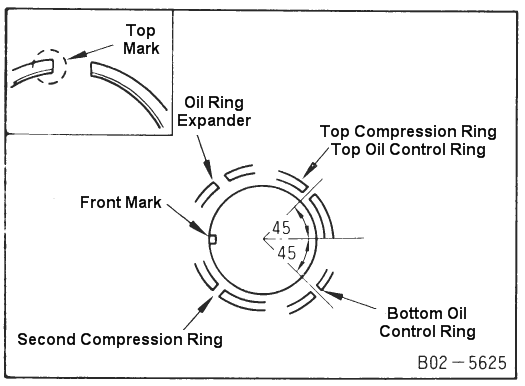
Repeat for all 6 pistons. Obviously the crank will get harder to turn each piston you install.
10) Turn the block upside down. Turn the crankshaft so one lobe is at BDC. Remove the bearing caps and plastigauge the bearings. Torque the caps in steps to 28-33 ft-lbs. Make sure you don't hit the oil holes for the bearings (like I did, below). Compare the clearances to the FSM (0.0011-0.0019"). Repeat for all 3 lobes. 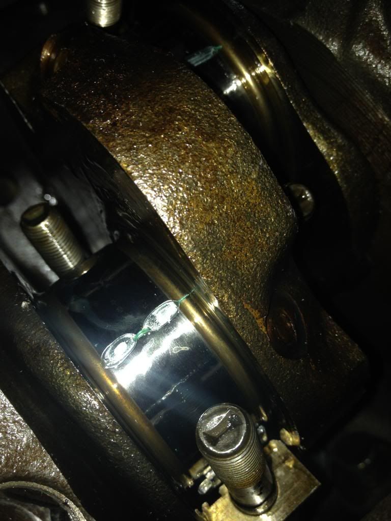
If all your clearances check out, clean off the plastigauge, apply a generous coat of assembly lube, and reassembly. Your rotating assembly is now complete. You can progress to "Engine Assembly"
VG30 DE(TT) Engine Assembly
------------------------------------------------------------------
1992 300ZX NA 5 Sp (Dead)
1990 300ZX NA Auto 2+2 (Dead)
1990 300ZX TT 5 Sp (Building)
2004 G35 Sport 6MT (DD) |


 VG30DE(TT) Short Block Assembly -