| Here's a little guide I put together while degreeing my engine. Please feel free to make suggestions or corrections. This was my very first time doing this and I felt overwhelmed at first. There are lots of guides and videos out there but not much on a four cam engine like ours. Hope this helps others who are interested in doing this. Special Tools:
-Degree Wheel
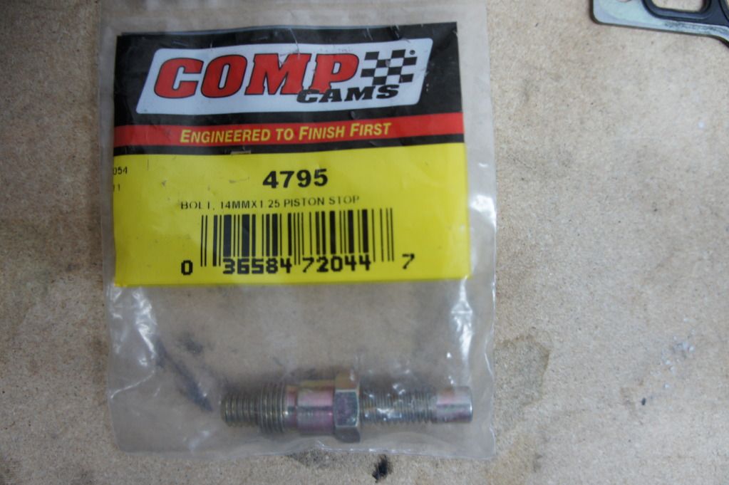
-Piston Stop
-Dial Gauge
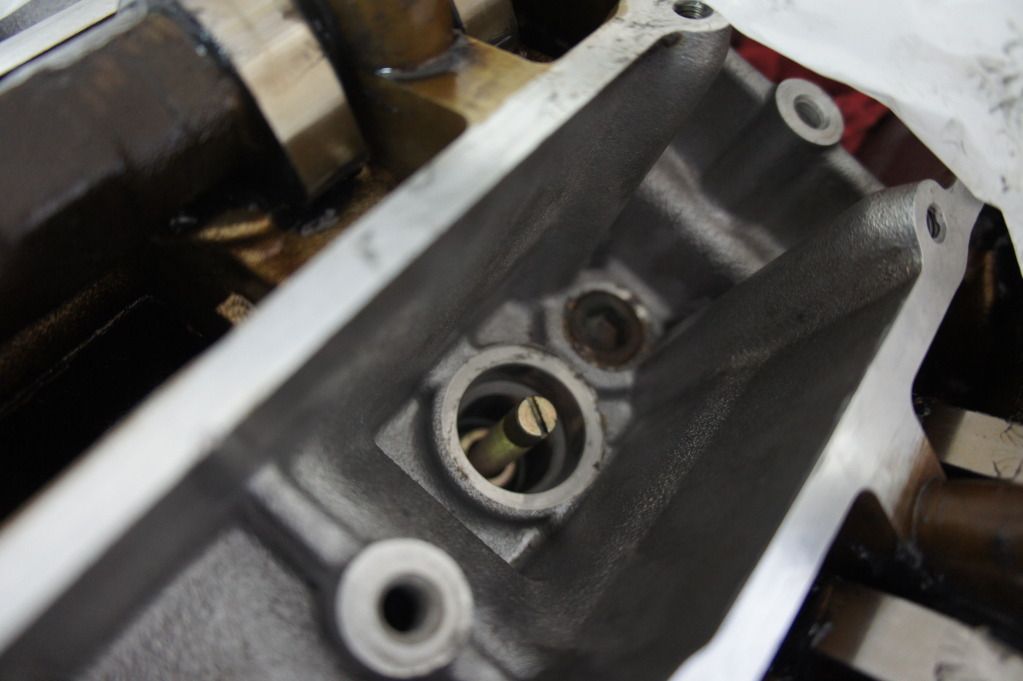
-Stiff wire(coat hanger works well) In this guide I am using stock cams. The procedure for JWT cams should be the same since they have the same center-line as stock cams. Stock intake cams have a center-line of 125 ATDC and a duration of 248 degrees. Stock exhaust cams have a center-line of 115 BTDC and a duration of 248 degrees as well. When degreeing a multi-cam engine you should follow the direction of the engine rotation starting with the first cam following the crank sprocket. This means we will degree the passenger side exhaust cam, passenger side intake cam, driver side intake cam and lastly the driver side exhaust cam. When degreeing the passenger side camshafts we will need to know exactly where top dead center of cylinder 1 is. When degreeing the driver side camshafts we will need to know exactly where top dead center of cylinder 2 is. This is a very important step and I urge you to not continue beyond this point if you are not completely confident that you have found it. EVERY READING YOU GET FROM YOUR DEGREE WHEEL WILL BE WORTHLESS IF YOU DO NOT GET THIS PART RIGHT! Step 1. Turn the crank until the piston in cylinder 1 is at what you believe to be the top of it's stroke. You can do this by turning the crank until the dot on the crank sprocket(and cam sprockets) line up with the notch on the oil pump/timing back plates or by simply looking through the spark plug hole with a flash light. Step 2. Loosen the crank bolt and rotate the degree wheel until your wire is pointing at 0 degree's. Tighten crank bolt. Step 3. Turn the crank 15 degree's counter clockwise or 15 BTDC. Install piston stop and turn it in towards the piston until it makes contact with the top of the piston. Step 4. Continue to turn the crank counter clockwise until the piston goes down and comes back up and lightly touches the piston stop. Take note of the degree wheel reading. Step 5. The mid point between the first reading(15 BTDC) and the second reading is the actual TDC of cylinder 1. Back the piston stop back out of the hole. Step 6. Rotate the crank until the pointer points to exactly the midpoint between these two points. Step 7. Loosen the crank bolt and rotate just the degree wheel until the wire points to 0 degrees. Re-tighten crank bolt. (Alternatively you can just bend the wire until it points to 0. I find this method better as you don't risk disturbing the crank while loosening and tightening the crank bolt). Congratulations, you have found TDC of cylinder 1. I highly recommend repeating steps 3-7 until you are satisfied you have TDC. If you did it right the piston will stop at exactly 15 before and after top dead center. Example: I used this piston stop I bought from amazon:
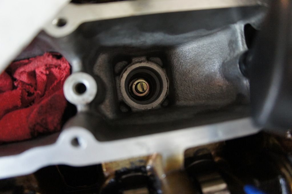
 This is what it looks like installed:
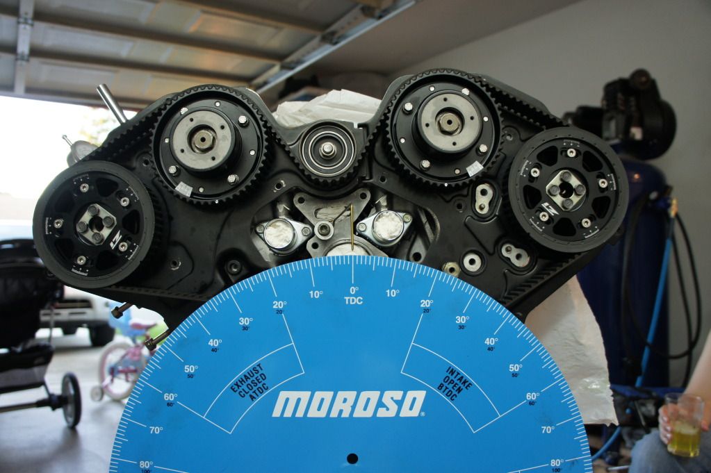
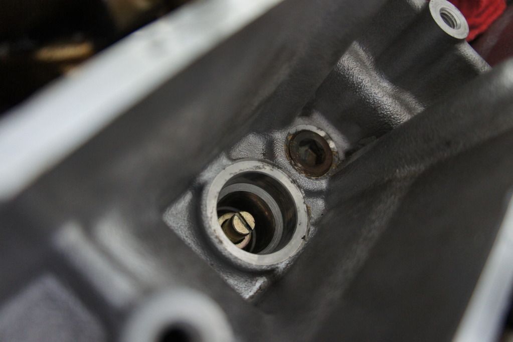
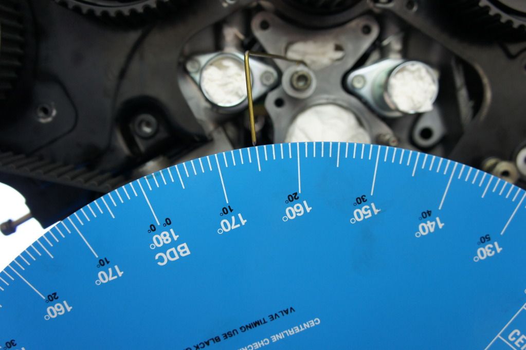
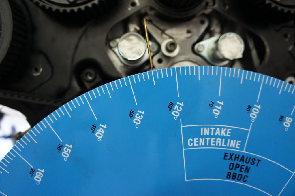
 In this picture I have rotated the engine until I had the first piston at what I believed was TDC. At this point I fasioned a pointer out of a old coat hanger and bent it to point at zero degree's:
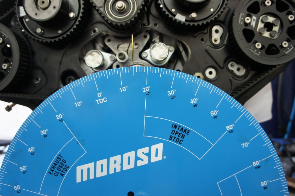
 In this picture I have rotated the engine exactly 15 degree's counter clockwise(opposite the running direction). After doing so I used my flat head screw driver to turn the piston stop down until it lightly made contact with the top of the piston:
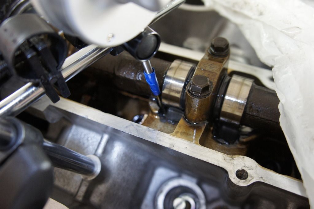
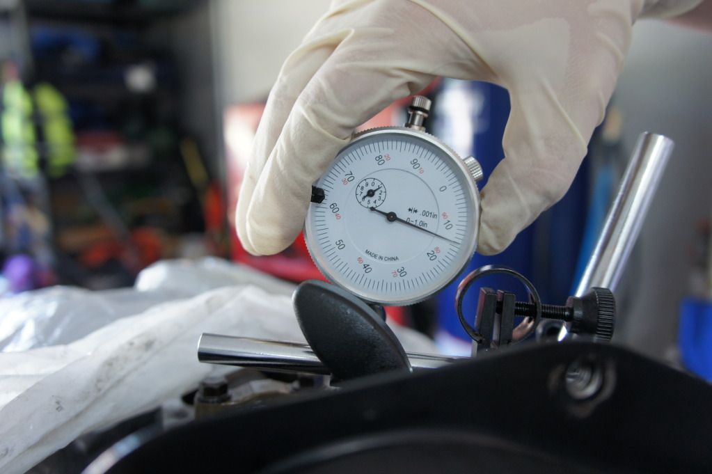
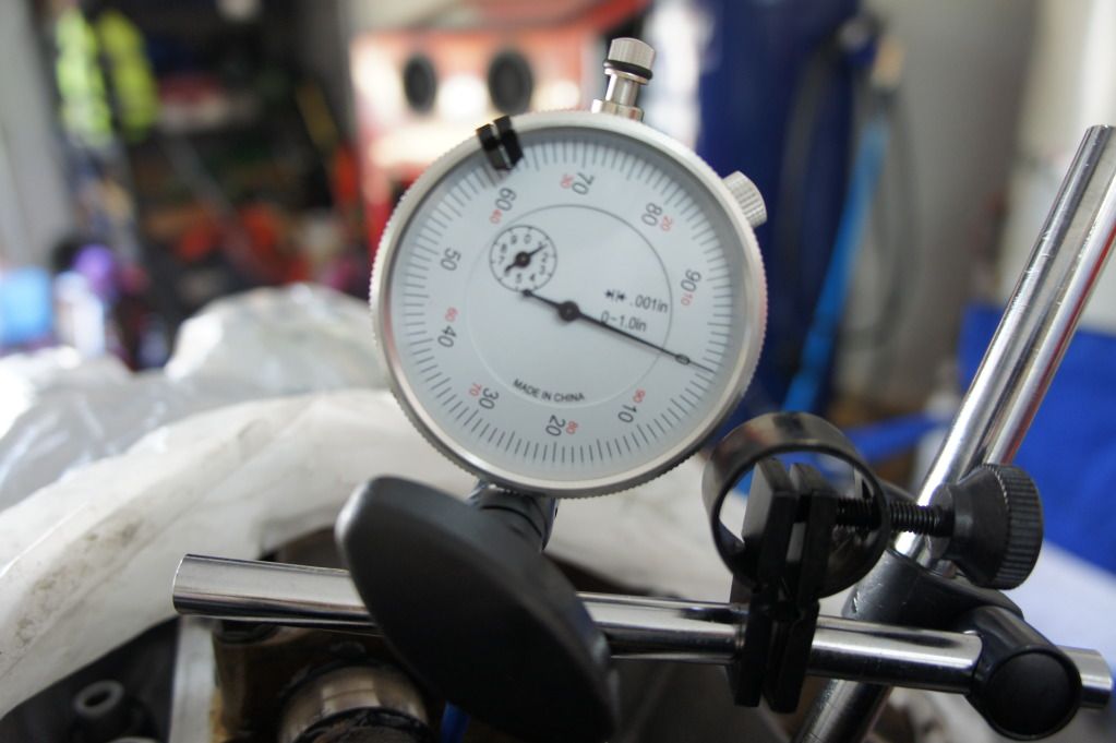
Don't be surprised when you don't get 15 degrees on both sides right away. Lets say you have 15 degrees BTDC(This is where you set the piston stop) and after continuing to rotate the crank counter clockwise you get 20 degrees ATDC. The exact midpoint between those two points is 2.5 degrees ATDC. You need to rotate the crank until the wire points to 2.5 degrees ATDC and then bend the wire to point at 0 degrees. Now that you have found TDC of piston one you can begin to degree the camshaft. It is tricky but you must set up your dial gauge to contact the top of the lifter on the cam you are trying to degree. It is important to get it to as close to parallel as possible with the valve being measured. Step 1. Turn the crank until the camshaft lobe is pushing the valve down. Install the dial gauge with a little pre-load. Step 2. Turn crank counter clock wise a bit past peak lift. Now turn it clock wise again and keep an eye on the dial gauge. You want to stop turning the crank when you have reached the peak of the cam lobe. You will know it because the dial gauge will be spinning one way and then right at the peak of the lobe or max valve lift the dial gauge will change direction. Any time you turn the crank too far do not simply back up to the spot you were shooting for...instead always back up a bit past your destination and then try again from the original direction Step 3. Stop turning the crank when you have found peak lift and zero out your dial gauge. Step 4. Slowly and smoothly begin to rotate the crank in either direction until the dial indicator shows .050". Take note of the angle of the degree wheel. Step 5. Turn the crank the opposite direction. You will see the needle on the dial gauge travel back to zero and as you begin to descend on the opposite side of the cam lobe the dial will again stop and change direction. It should change direction at exactly 0.0" on the dial gauge. Continue turning the crank until the dial gauge shows .050" again. Take note of the angle of the degree wheel. Step 6. The exact midpoint between the two degree wheel readings you found is the center-line of the cam. If you rotate the crank to this midpoint your dial gauge should show 0.0" again. Step 7. Adjust camshaft sprocket and repeat steps 2-6 until you achieve the proper center-line. Keep in mind that one degree of ajustment on the camshaft sprocket equals two crank shaft degrees. Example: Here are a few pictures of my dial gauge mounted:
 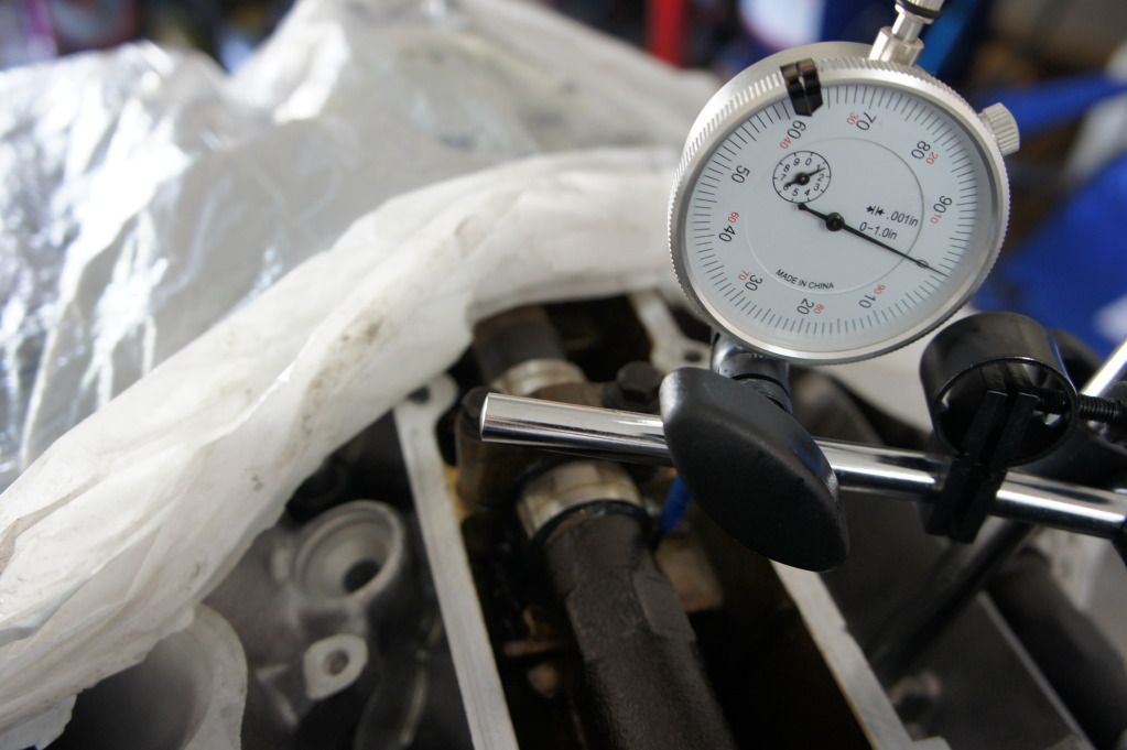
In this picture I have determined the peak valve lift happened on my dial gauge at about .033". This number is not important. 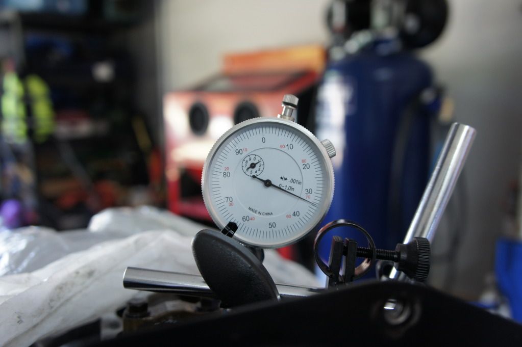
Zero out the dial gauge:
 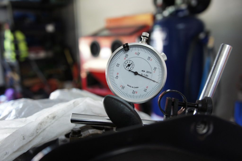
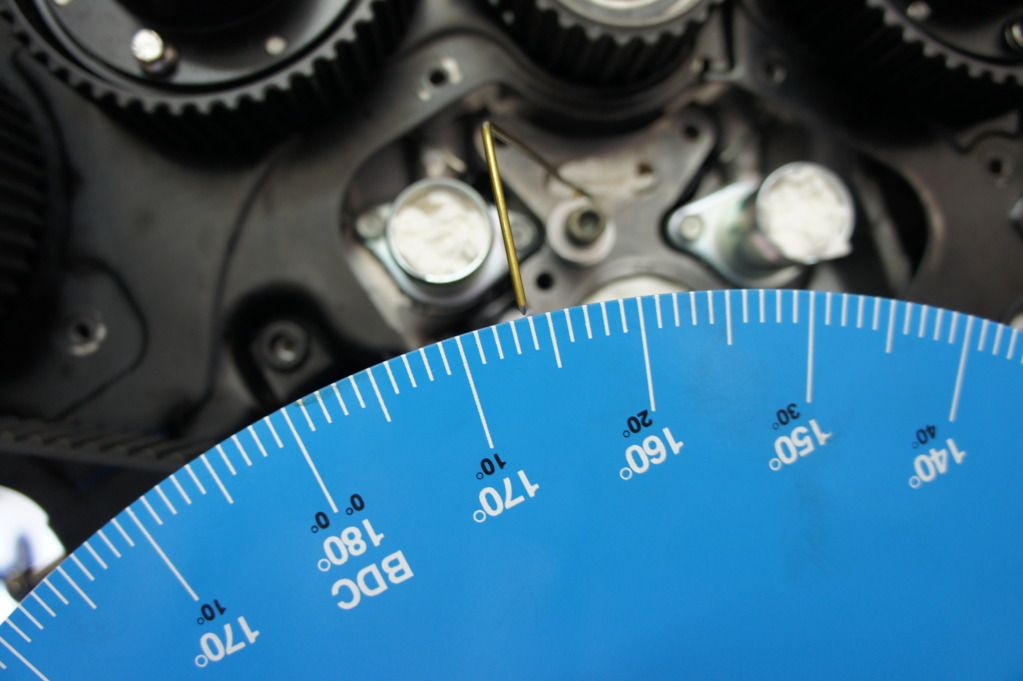
Rotate the engine in either direction until the dial gauge shows .050". My degree wheel reading is 165 ATDC:
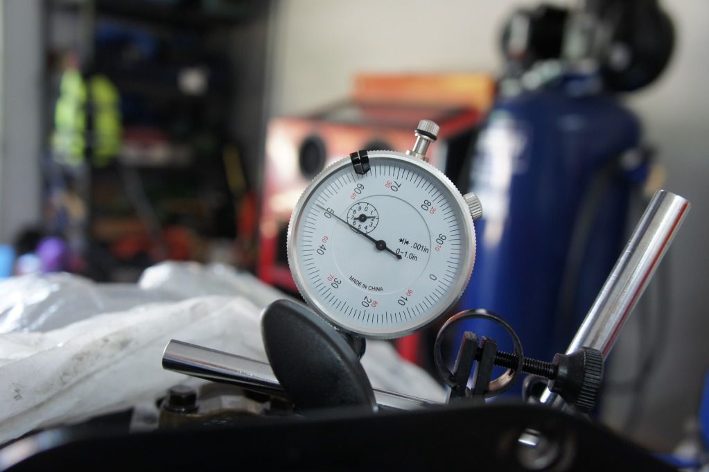 
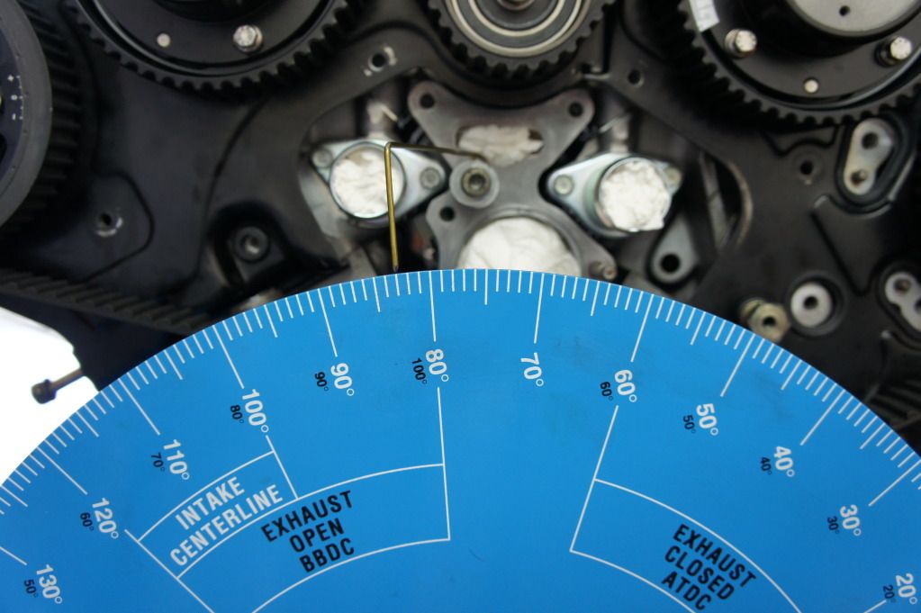
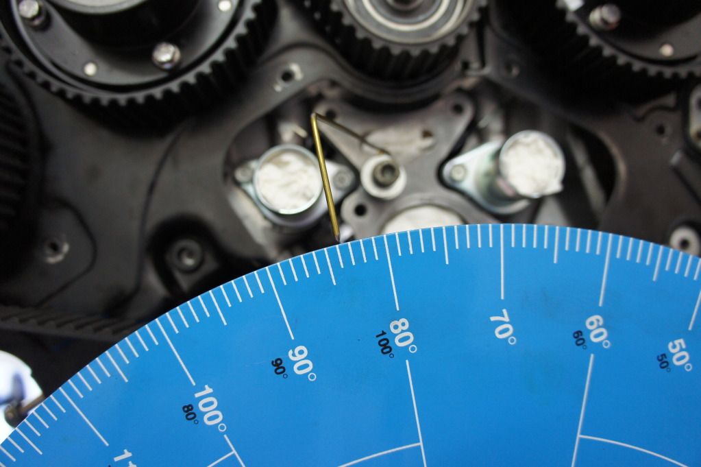
Rotate the engine in the opposite direction until the dial gauge shows .050" again. My degree wheel reading is 83 ATDC:
 The exact midpoint between those two readings is 124 ATDC. Since I am degreeing the intake cam shaft which has a center-line of 125 ATDC this camshaft is advanced by 1 crank shaft degree. The sprocket only needs to be retarded by .5 degree's. After adjusting the sprocket again I get: 166.25 ATDC:
 and 83.75 ATDC:
 The exact midpoint between these two readings is...125 ATDC! Rotate the crank to 125 ATDC and the dial gauge shows 0.0" which is what we should expect.
Well, that's pretty much it. The only other thing I would like to mention is that when you go to degree the driver side camshaft's you need to first find TDC of cylinder #2 just like we did for cylinder #1 using the piston stop except in step 3 and 4 you will need to go clock wise instead(turn crank 15 degrees ATDC or clockwise, set piston stop and then continue turning clockwise).
For those that are curious my stock engine(probably rebuilt at some point) and stock cams needed the following adjustments: Passenger side exhaust: Retard by 2.5 camshaft degree's
Passenger side intake: Retard by 2.25 camshaft degree's
Driver side intake: Retard by .4375 camshaft degree's
Driver side exhaust: Advance by 1.5 camshaft degree's
|


 A guide to VG cam degreeing -