| Well i recently installed an alarm, without realizing the Z had two actuators already i purchased and installed an external actuator (months ago, to prepare for the alarm install) Recently the actuator died, so i decided to go the stock route, and wire the alarm into the stock signal wire to unlock/lock the doors. Unfortunately im not sure i fully understand this diagram. 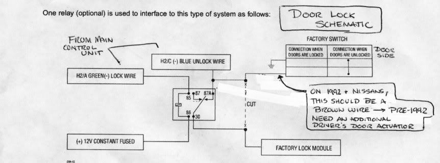
My alarm Control has two wires: Blue: - Unlock, + Lock
Green: + Unlock, - Lock Can someone tell me what signal causes what function through this brown wire (negative unlock, interrupt lock?) And what draw might this see? My alarm lock/unlock wires support 200mA. Thanks.
|


 92+ Power Door Locks Wiring -
  18:57:48 09/02/09