| After tinkering with this project on and off since the summer, I finally have it to a point where it's actually worth posting about :) I initially became inspired while searching on here for e-fan controller setups to use with my Maxima E-fan. I never liked any of the off-the-shelf e-fan controllers, and I ran across a post from a member who was using an Arduino to run a PI loop to control the E-Fan speed which intrigued me. As I started playing with the Arduino more, the project scope increased into something that I'm really happy with :) Cliffnotes on what it currently does:
-Arduino Uno; gets power from the OEM clock harness
-Adafruit data logging shield
-Adafruit tri-axial accelerometer
-I tapped into the OEM CTS sensor voltage @ the ECU
-An AEM 0-100psig sensor will replace the OEM OPSU
-The Uno drives the gauge cluster Coolant Temp and Oil Pressure gauges
-Logs any reading or parameter that I want to an SD card at a configureable frequency
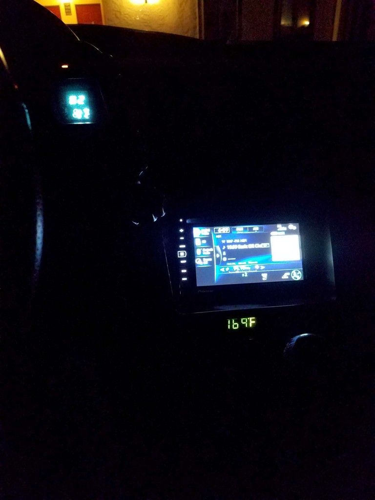
-A gutted OEM clock is converted into a digital readout. The "reset" button feed back into the Arduino to let me change what sensor reading is displayed Planned Enhancements:
-Once spring comes and I can collect baseline coolant temp data, I'll install my maxima e-fan and tune the PID loop
-I already have provisions in the hardware and software to add a boost sensor to control a boost control PID loop; so someday I hope to finally do a TT swap on my slicktop to see if I can get decent boost control from it Here is a demo video of the Sensor reading and gauge control functionality. For this demo, I have an OEM CTS hooked up to a spare ECU with the Arduino tapped into it using a homemade boomslang-type harness. The AEM pressure sensor is hooked up to a PVC pressure vessel that I pressurized to ~50psi beforehand. The OEM clock is showing the coolant temp reading.
La-Z-Link And a short demo video showing the clock reset button working (it needs a bit of tweaking to make it work better, but it's pretty much there):
La-Z-Link Onto some tech details for anyone interested
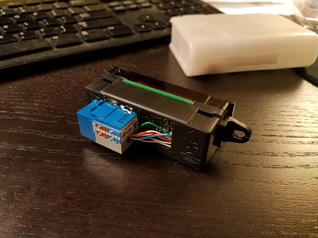
The only part of the clock I reused was the housing. I fabbed a replacement upper and lower PCB out of protoboard. A pair of 8-bit shift registers turn on and off the segments as commanded by the Arduino. The 4-position display is a common-cathode type. Power, Ground, "reset button", and shift register signals are passed to the Arduino over CAT5. 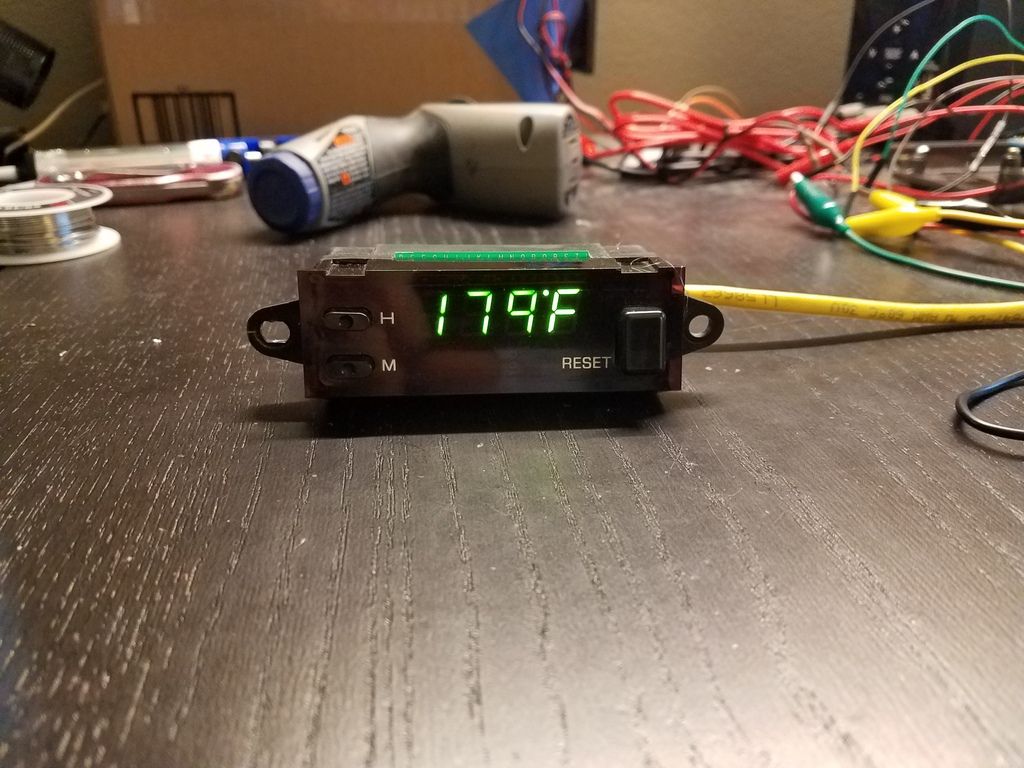
Controller Details
Adafruit makes a decent little molded case for the Arduino Uno that i used to mount the Uno, datalogging shield, and accelerometer (the little PCA behind the SD Card) I mounted TE Amp connectors on the back wall to make it easy to install/remove. The coin-cell battery is for the Real-Time Clock to allow me to timestamp the logfiles, although it eats up 2 analog inputs, so I might have to ditch it.
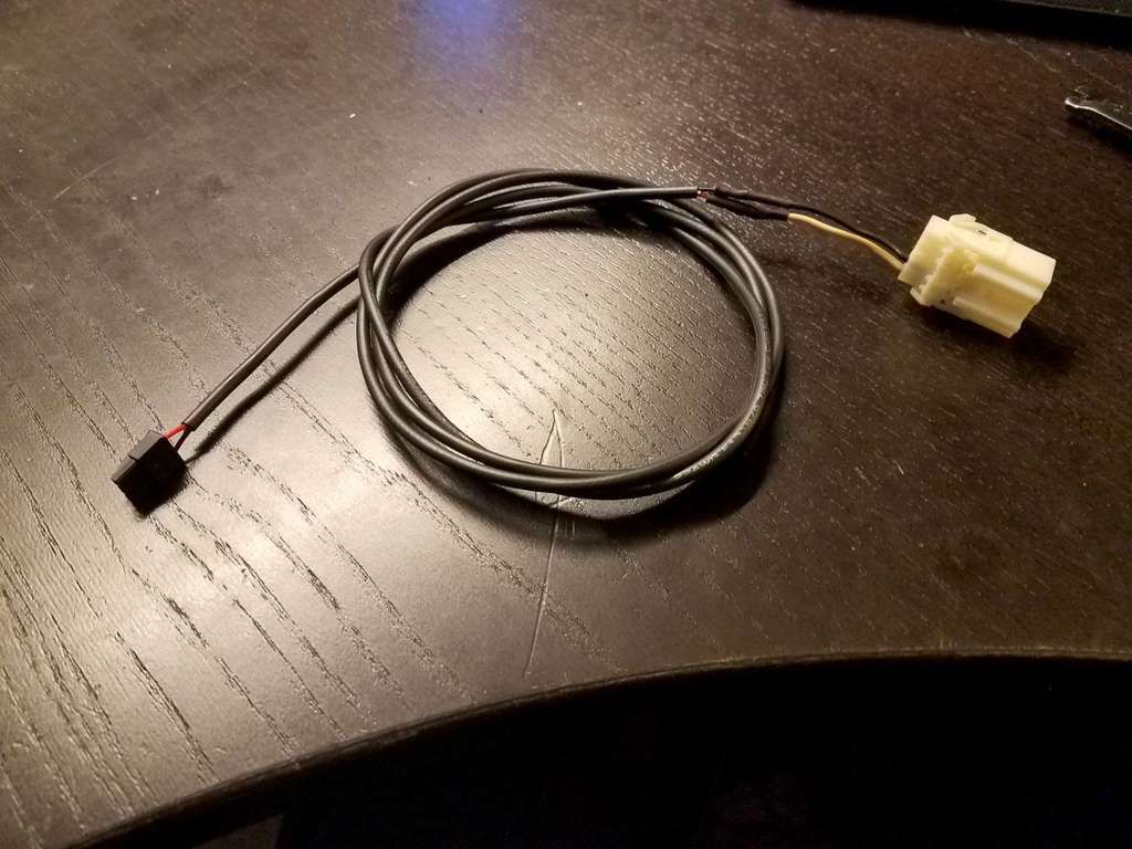
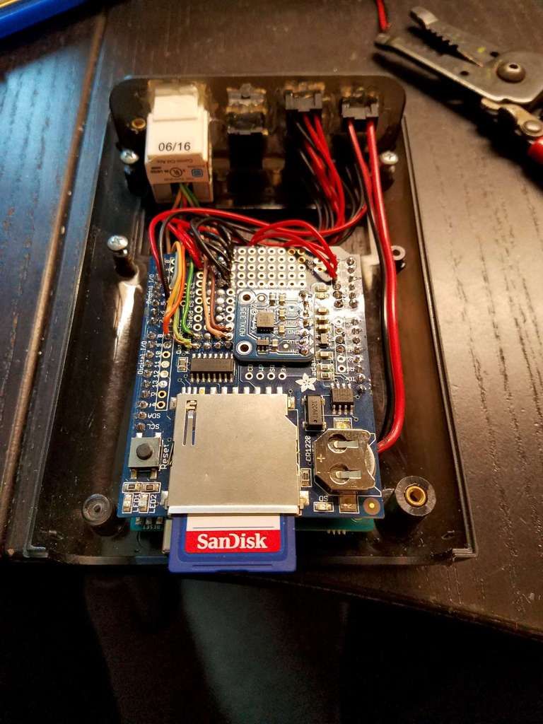 I reused the plug from the OEM clock to make a power harness for it (yes, I know I need to add a fuse)
|


 My Arduino multi-gauge/datalogger/e-fan controller project -