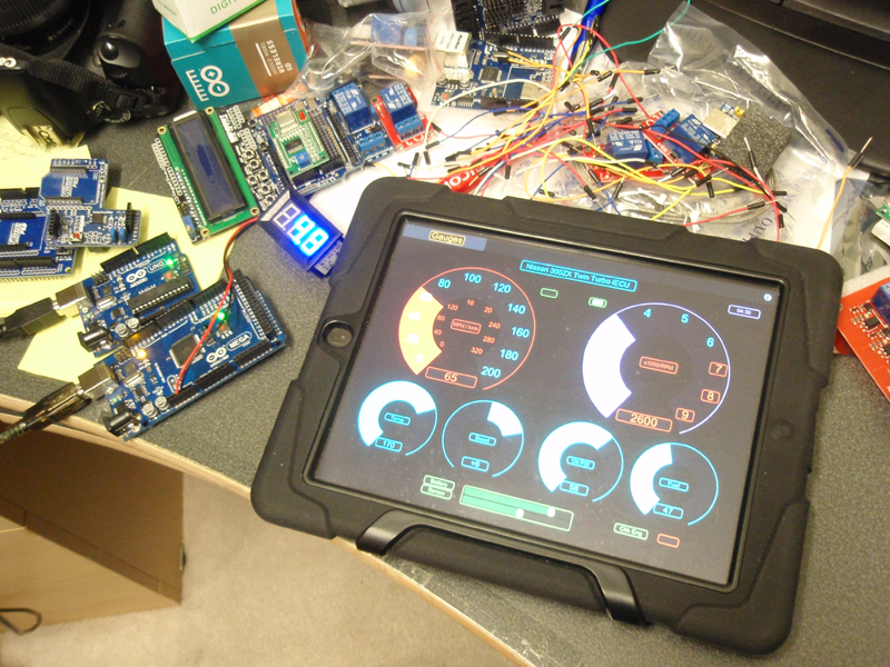
| I'm so stoked about this project I don't even know where to begin :) Here are a few pics and a little bit of description of what's going on. The project is using Arduino microcontrollers to control everything. One mega arduino has 16 analog inputs, 28 digital inputs and 12 PWM outputs. It has 4 RX/TX I/O's and an SDA and SCL. There's also on-board voltages for 5 and 3 volts as well as some selectable configurations and connection to a computer (when needed) via USB. The way everything in this project is running is on a network. The arduino is very flexible and there are many accessories being made for it. One of which is a wireless network server/client module kit. This allows it to be on it's own network without needing a computer. You use a computer to program the network IP and port settings of the network module and then you remove it from it's interface to computer (part of the kit) and then plug it into the arduino to make it a standalone wireless network. I've already got things to work but right now I'm just controlling little things like LEDs and using a potentiometer between the on-board power supply to the arduino inputs to simulate gauge voltage in order to see the gauges on the ipad work. The app on the ipad is programmed with an IP for the network and the ports for in/out traffic to match the arduino wireless network. The arduino draws very little power in standby mode (not supplying voltage to anything) so you can leave it connected to a car battery if you have it in your car. Or you can provide switched power, it's up to you.
 Here is a picture of the gauge page. I'm still designing everything so right now I'm playing with a few colors. These pictures show a simulation of how it will look when it's all together and working. 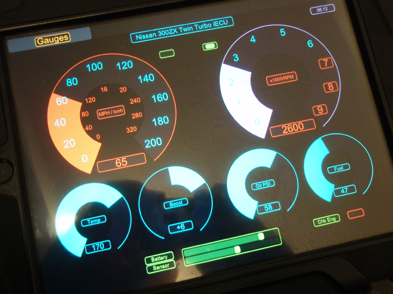
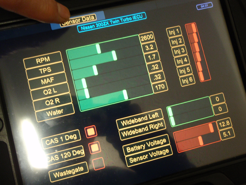
The next page is more sensor data information. As you can see, all the sensors here are voltages applied to the ECU which you can easily tap from and do not require a computer to do software byte calculations. The speed and RPM signals are not direct voltages but they are easy to code into the arduino since they are just on/off pulses. Those signals as well as the other gauge cluster gauge signals can be taken right off the back of the gauge cluster or from the harness. I'm also in the process of adding another page which instead of reading voltages will allow you to send voltages to the ECU pins for simulating sensor operation. If anyone saw my post where I post a picture of the hardware SIM/Mon I built for doing this, this is the same thing only being controlled by the app and arduino voltage outputs. This can come in handy to simulate engine temperatures, TPS voltages and MAF voltages to help in diagnosing where you may be having a problem when your engine isn't quite running right.
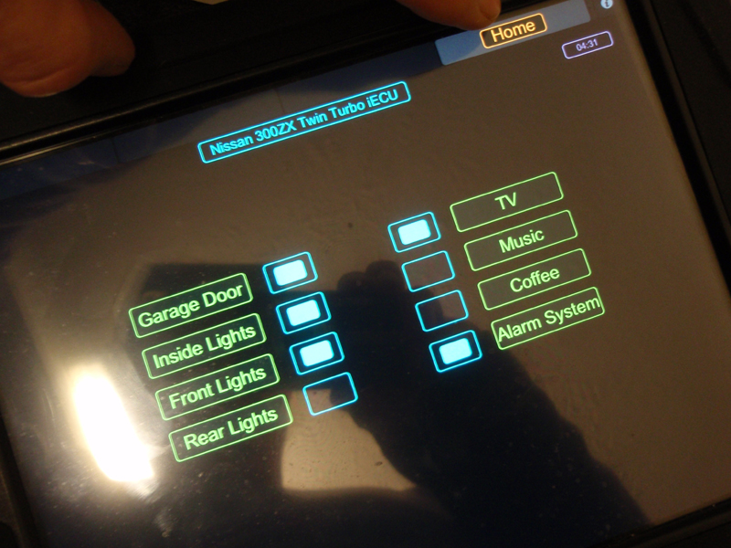
 The next page is where you have the option to connect relays to different things in your car. From inside your house you can turn these things on and off.
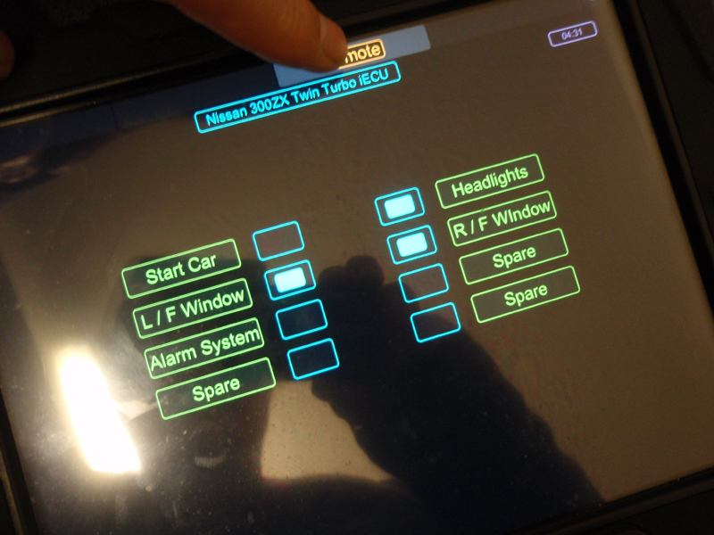 The next page is the home page. With additional arduinos on the same network in your home, you will be able to drive in your garage and join the network to turn things on or off which you have connected to some very easy to connect add-on relays for the arduino.
 Well, that's about it for right now. If only I had about three months vacation. I could get so much done with this. If anyone has any ideas please let me know. I want to put as much into it as I can and It's only limited by your imagination. Humm...now where did I put that stepping motor, got to get back to adding that boost controller :)
 www.mytwinturbo.com Nissan Data Voice - The first Nissan diagnostic software with a voice!
 Download my Nissan 300ZX Vin/Model Lookup. Watch an ECZA meet caravan! |


 iECU part 2. -